
约 63164 个字 预计阅读时间 211 分钟
Structure
---Day2---
Overview
Structure Objects Demonstration——讲解
结构对象演示
- Member Systems and Member Parts
- Linear Member
- Curved Member Frame Connection
- Assembly Connections
- Slabs
- Placed Wall
- Objects Placed in a Model
- Designed Equipment
-
Import Export Summary
-
构件系统和构件部件
- 线性构件
- 弯曲构件框架连接
- 装配连接
- 板
- 放置墙
- 放置在模型中的对象
- 设计设备
- 导入导出摘要
Place Members
In this course, you will learn the procedure for placing linear and curved members individually using frame connections that maintain positioning design intent.
在本课程中,您将学习使用保持定位设计意图的框架连接单独放置线性和弯曲构件的过程。
After completing this course, you will be able to:
完成本课程后,您将能够:
- Place linear members using frame connections.
-
Place curved members using frame connections.
-
使用框架连接放置线性构件。
- 使用框架连接放置弯曲构件。
Place Members Overview Demonstration —— 讲解
放置构件概述演示
Today, we will look at placing linear and curved members individually using frame connections that maintain member positioning design intent.
今天,我们将研究如何使用框架连接单独放置线性和弯曲构件,以保持构件定位设计意图。
After a member system is created using the Place Linear Member System command, you can split it into multiple member parts.
使用“放置线性构件系统”命令创建构件系统后,您可以将其拆分为多个构件部分。
The command allows you to position the ends of the member system using frame connections. Frame connections define the connection and positioning of the member systems relative to each other, to the grid lines, to the object surfaces, or simply to a point in space.
该命令允许您使用框架连接定位构件系统的末端。框架连接定义构件系统相对于彼此、网格线、对象表面或空间中某个点的连接和定位。
The overall purpose of a frame connection is to define a structural model that will adjust appropriately as you move the members and change member sizes.
框架连接的总体目的是定义一个结构模型,该模型将在您移动构件和更改构件尺寸时进行适当调整。
【
For example, the seated frame connection positions the supported member on the top or bottom of the supporting member, regardless of the cardinal points used. The member system ends can have different types of frame connections. When placing a member, select the type of frame connection that represents your engineering design intent. You can also let the software select the appropriate frame connection by using the By Rule option. When a member is placed using frame connections, no interference is reported between the supported and the supporting members. You can place a curved member system by using the Place Curve Member System command.
例如,无论使用哪个基点,固定框架连接都会将支撑构件定位在支撑构件的顶部或底部。构件系统末端可以具有不同类型的框架连接。放置构件时,选择代表您的工程设计意图的框架连接类型。您还可以让软件使用“按规则”选项选择适当的框架连接。当使用框架连接放置构件时,支撑构件和支撑构件之间不会报告任何干扰。您可以使用“放置曲线构件系统”命令放置弯曲构件系统。
The curved member ends can be positioned only by the Axis-Along or Unsupported frame connections. Assembly connections are used to trim the connected member parts to the correct length. The steel-detailing design phase assures that the members have the required end-cuts. Steel detailing can be accomplished within the application by using customized assembly connections, or created using a third-party program.
弯曲构件端部只能通过沿轴或不受支撑的框架连接来定位。装配连接用于将连接的构件部分修剪到正确的长度。钢结构详图设计阶段可确保构件具有所需的端部切口。钢结构详图可以在应用程序中通过使用自定义装配连接来完成,也可以使用第三方程序创建。
】
Place Columns Demonstration——【操作】U04,放置柱,记得属性修改材质
放置柱演示
This video demonstrates placing columns at the intersection of grid lines.
此视频演示了如何将柱放置在网格线的交叉点。
When placing structural members, we recommend that you use grids. Although grids are not required, they help in the modeling process by providing reference locations for member ends, instead of trying to place members in free space. In addition, when a grid line is moved by changing the location of the associated grid plane, all objects associated with that grid line move too. This makes modeling modifications quick and easy.
放置结构构件时,我们建议您使用网格。虽然网格不是必需的,但它们有助于建模过程,因为它为构件末端提供了参考位置,而不是试图将构件放置在自由空间中。此外,当通过更改相关网格平面的位置来移动网格线时,与该网格线相关的所有对象也会移动。这使得建模修改变得快速而简单。
Define your workspace to include A2, U04 CS. Click Tasks, Structure to switch to the Structure task. Set the Active Permission Group to Structural. Click Place Linear Member System on the vertical toolbar to open the command ribbon. In the Connection box, select a frame connection type to be used for positioning the member.
定义您的工作区以包括 A2、U04 CS。单击“任务”、“结构”以切换到“结构”任务。将“活动权限组”设置为“结构”。单击垂直工具栏上的“放置线性构件系统”以打开命令功能区。在“连接”框中,选择用于定位构件的框架连接类型。
The last frame connection you used will be the default. Select By Rule to have the software automatically select a frame connection type based on the member type and the start and end points selected. You can manually select the frame connection from the Catalog by using More.
您使用的最后一个框架连接将是默认连接。选择“按规则”可让软件根据构件类型和所选的起点和终点自动选择框架连接类型。您可以使用“更多”从目录中手动选择框架连接。
In this example, we will select the intersection of grid lines for the member's two ends. In this case using By Rule, the command will select the Unsupported frame connection. However, the frame connections have associated SmartSketch relationships to the grid intersection points.If you modify the position of either grid plane, the position of the member is updated automatically.
在此示例中,我们将选择构件两端的网格线交点。在本例中,使用“按规则”,命令将选择“不受支持的框架连接”。但是,框架连接与网格交点具有关联的 SmartSketch 关系。如果修改任一网格平面的位置,构件的位置将自动更新。
The System option identifies the parent system for the member, with the default being the last system that you used selected. Besides the systems that you've recently selected, you can use More to select any system in the workspace or database. Click More. Expand A2, U04 and select the Columns system to define that location in the hierarchy for the columns. For Type, select Column.
“系统”选项标识构件的父系统,默认为您选择的最后一个系统。除了最近选择的系统之外,您还可以使用“更多”选择工作区或数据库中的任何系统。单击“更多”。展开 A2、U04 并选择“柱”系统以定义柱在层次结构中的位置。对于“类型”,选择“柱”。
The Member type categories are broad groups of member types defined in the Catalog. The column type category contains the column and stud member types. When placing a member, select a member type category and then a member type. The member type is used when generating drawings and reports. Type the section name W14x43 in the Section box. Recently used sections, filtered based on the selected member category and type, are in the drop-down list. This list of last-used section sizes is stored in the session file. You can enter the full section name to identify the cross section from the Catalog. You can also look up the section by entering part of the name with a search character and then selecting the section name in the Select Section dialog. For example enter W14*.
构件类型类别是目录中定义的构件类型的大组。柱类型类别包含柱和螺柱构件类型。放置构件时,选择构件类型类别,然后选择构件类型。构件类型用于生成图纸和报告。在“截面”框中键入截面名称 W14x43。根据所选成员类别和类型筛选的最近使用的部分位于下拉列表中。此上次使用的截面尺寸列表存储在会话文件中。您可以输入完整的截面名称以从目录中识别横截面。您还可以通过使用搜索字符输入部分名称,然后在“选择截面”对话框中选择截面名称来查找截面。例如,输入 W14*。
For the Cardinal Point, select 5-Center. There are 15 cardinal positions available. The location of the cardinal points 10 (center-of-gravity) and 15 (shear center) depend on the shape of the section.
对于基点,选择 5-中心。有 15 个基点可用。基点 10(重心)和 15(剪切中心)的位置取决于截面的形状。
The Angle option defines the angle by which the cross-section is rotated about the local axis of the column. The Reflect option mirrors the cross-section about the local z-axis of the member. This option affects both symmetric and asymmetric sections. You can use this option when you want the flanges of a channel section to point in the opposite direction.
“角度”选项定义横截面绕柱的局部轴旋转的角度。“反射”选项将横截面镜像到构件的局部 z 轴。此选项会影响对称和不对称截面。当您希望槽钢截面的法兰指向相反方向时,可以使用此选项。
Click Properties on the ribbon to open the Member Properties dialog. Click the Cross Section tab. Select Steel-Carbon and A36 in the Material and Grade properties, respectively. Click okay to save the settings. If you set the Material and Grade properties before placing a structural member during a session, the values of these properties are retained throughout the session. Save your session file to retain the values for next time. This allows you to typically define the material and grade only once for a given session file.
单击功能区上的“属性”以打开“构件属性”对话框。单击“横截面”选项卡。在“材料”和“等级”属性中分别选择“钢-碳”和“A36”。单击“确定”以保存设置。如果在会话期间放置结构构件之前设置了“材料”和“等级”属性,则这些属性的值将在整个会话期间保留。保存会话文件以保留这些值以供下次使用。这允许您通常只为给定的会话文件定义一次材料和等级。
When you are in the smartstep of a command, the SmartSketch relationship points are active. You can select which points you want to locate by setting the options on the SmartSketch page of the Tools, Options dialog. We recommend that you select a minimalist set of options to help reduce the chance of creating unwanted SmartSketch relationships. Note that software prompts are displayed at the bottom of the window. Move your cursor to the intersection of two grid lines to define the column's starting point. The intersection glyph appears. Click to place the column's start point.
当您处于命令的智能步骤中时,SmartSketch 关系点处于活动状态。您可以通过在“工具”、“选项”对话框的 SmartSketch 页面上设置选项来选择要定位的点。我们建议您选择一组最基本的选项,以帮助减少创建不必要的 SmartSketch 关系的机会。请注意,软件提示显示在窗口底部。将光标移动到两条网格线的交叉点以定义柱的起点。出现交叉点符号。单击以放置柱的起点。
For consistency, columns should be placed with first point at the lower elevation and the second point at the higher elevation. Specify the end point of the column. After you enter the second point, the command cycles back, uses the second point you just indicated as the first point of the next member, and prompts you to enter the second point of the next member. The command will then continue to cycle, repeatedly prompting you to enter the second point of the next member. This continues until you click the first point smartstep to indicate you want to identify a different first point. This second point only method is called the Continuous Placement.
为了保持一致性,柱应将第一点放置在较低的海拔高度,将第二点放置在较高的海拔高度。指定柱的终点。输入第二个点后,命令将循环返回,使用您刚刚指示的第二个点作为下一个成员的第一个点,并提示您输入下一个成员的第二个点。然后,命令将继续循环,反复提示您输入下一个成员的第二个点。这种情况将持续下去,直到您单击第一个点智能步骤以指示您想要识别不同的第一个点。这种仅第二点的方法称为连续放置。
The Advanced Member Positioning icon, A+, is used to place a member at the intersection of three objects and maintain the relationship to those objects. For example, a column that needs to stay over two walls, or bulkheads, objects and maintain the relationship to those objects. For example, a column that needs to stay over two walls, or bulkheads, on a lower level. You must select the Align-Default or Align-Lapped frame connections to use the advanced member positioning options.
高级构件定位图标 A+ 用于将构件放置在三个对象的交叉点处并保持与这些对象的关系。例如,需要停留在两面墙或舱壁上方的柱子,并保持与这些对象的关系。例如,需要停留在较低水平的两面墙或舱壁上方的柱子。您必须选择对齐默认或对齐搭接框架连接才能使用高级构件定位选项。
The Finish Mode option specifies whether or not Finish must be selected to place a member in the model. If Finish Mode is selected, the software places the member in tentative mode after you identify the second end point. This tentative mode allows you to modify placement settings such as the offset, cardinal point, or frame connection properties before you commit the member to the model. If the Finish Mode is not selected, then the software automatically places the member in the model after you identify the second end point. Undo the placement of the horizontal columns we placed. As a rule, when placing horizontal members you should always change your Type Category and Type to Beams first. Place columns at the three other grid corners.
完成模式选项指定是否必须选择完成才能将构件放置在模型中。如果选择了完成模式,则软件会在您确定第二个端点后将构件置于暂定模式。此暂定模式允许您在将构件提交到模型之前修改放置设置,例如偏移、基点或框架连接属性。如果未选择完成模式,则软件会在您确定第二个端点后自动将构件放置在模型中。撤消我们放置的水平柱的放置。原则上,放置水平构件时,应始终先将类型类别和类型更改为梁。将柱子放置在其他三个网格角。
Contiguous Placement Demonstration——【操作】鼠标中键,Beam,连续放置
连续放置演示
This video demonstrates placing four beams between columns in Unit U04 by using the Contiguous Placement method.
此视频演示了如何使用连续放置方法在单元 U04 的柱之间放置四根梁。
Before we begin, we should discuss a very useful technique for placing members so they always retain solid relationships between their surrounding members. This is referred to as the middle-click mouse technique. Start by choosing Place Linear Member on the vertical toolbar. On the command ribbon, set System to A2, U04, Structural, Beams. Set the member type category and type to Beam. Set Section name to W16x67. Set Cardinal point to 8, and Material to Steel-Carbon with Grade set to A36.
在开始之前,我们应该讨论一种非常有用的放置构件的技术,以便它们始终保持与周围构件之间的牢固关系。这被称为鼠标中键技术。首先在垂直工具栏上选择“放置线性构件”。在命令功能区上,将系统设置为 A2、U04、结构、梁。将构件类型类别和类型设置为梁。将截面名称设置为 W16x67。将基点设置为 8,将材料设置为钢碳,等级设置为 A36。
Hover the cursor over the first column until you see a purple dotted line appear vertically along the middle of the member. Press your mouse wheel or middle mouse button to middle-click and lock the line. This represents the point on the member where relationships like frame connections are first formed. By using the middle-click technique, you can always create such connections between members, ensuring your structure will remain solid in the event a change becomes required on its dimensions.
将光标悬停在第一列上,直到看到一条紫色虚线垂直出现在构件中间。按下鼠标滚轮或鼠标中键单击并锁定该线。这表示构件上首次形成框架连接等关系的点。通过使用鼠标中键单击技术,您始终可以在构件之间创建此类连接,从而确保在需要更改结构尺寸时,结构仍能保持稳固。
Now, hover your cursor over the horizontal grid line which you will run your next member along. Left-click to set the first point of the first beam (the intersection of the column's purple line and the grid line). Now, run your member over to the next column.
现在,将光标悬停在水平网格线上,您将沿着该网格线放置下一个构件。左键单击以设置第一个梁的第一个点(柱的紫色线和网格线的交点)。现在,将您的构件移到下一柱。
On this column, perform the same middle-click selection of the vertical dotted line. After it is locked, hover over the next grid line that you want to place a beam. Like before, the grid line will turn purple and dotted. Left-click to select the second point of the first beam and--so long as the Finish Mode is not selected--the beginning of the next beam.
在此柱上,执行相同的鼠标中键单击选择垂直虚线。锁定后,将鼠标悬停在要放置梁的下一个网格线上。与之前一样,网格线将变为紫色和虚线。左键单击以选择第一个梁的第二个点,并且(只要未选择“完成模式”)选择下一个梁的起点。
By also employing the middle-click mouse technique, you can be sure that not only is your beam placement tasks performed efficiently, they will always have the proper relationships established with their corresponding members.
通过使用鼠标中键单击技术,您不仅可以高效地执行梁放置任务,而且它们将始终与相应的构件建立正确的关系。
Frame Connections Demonstration——讲解
框架连接演示
Frame connections describe the positioning relationship between member systems. This positioning relationship defines the member orientation and offset of the supported member in relation to the supporting member. Two frame connections are placed when you place the member system, one at each end. Because frame connections define relationships between member systems, the frame connection might prevent you from moving a member. When placing a member, you can select the frame connection that you want manually, or you can use the By Rule option to have the software select the most appropriate frame connection based on the supporting and supported members. You can customize the rule-based frame connection selection routines.
框架连接描述了构件系统之间的定位关系。此定位关系定义了受支撑构件相对于支撑构件的构件方向和偏移。放置构件系统时,会放置两个框架连接,两端各一个。由于框架连接定义了构件系统之间的关系,因此框架连接可能会阻止您移动构件。放置构件时,您可以手动选择所需的框架连接,也可以使用“按规则”选项让软件根据支撑构件和受支撑构件选择最合适的框架连接。您可以自定义基于规则的框架连接选择例程。
You can also select another member's frame connection as the start or end location of the member that you are placing. The two member ends can have different frame connection types, including one end as Unsupported. Set the Locate filter to Member System and click a member system. The software highlights all objects related to the member's frame connections. This is a quick way to confirm that the selected member system is connected by its frame connections to the appropriate objects. The frame connection is an optional relationship.
您还可以选择另一个构件的框架连接作为要放置的构件的起点或终点。两个构件端可以具有不同的框架连接类型,其中一端为“不受支撑”。将“定位”过滤器设置为“构件系统”,然后单击一个构件系统。软件会突出显示与构件的框架连接相关的所有对象。这是一种快速确认所选构件系统通过其框架连接连接到适当对象的方法。框架连接是可选关系。
Therefore, when you copy-paste a member, you can optionally re-establish the frame connection relationship to members outside of the copy set, or delete the relationship and replace it with an Unsupported frame connection. You will need to experiment with different types of frame connections to fully understand their behaviors and the situations where they are most useful. There are three classes of frame connections based types of frame connections to fully understand their behaviors and the situations where they are most useful. There are three classes of frame connections based on the number of supporting members. The Unsupported and Surface frame connections require no supporting members. The Seated, Flush, Tangent, and Axis frame connections require a single supporting member as input. The Gap and Vertical Corner Brace frame connections require two or more supporting members as input.
因此,当您复制粘贴构件时,您可以选择重新建立与复制集之外的构件的框架连接关系,或删除该关系并将其替换为不受支持的框架连接。您需要尝试不同类型的框架连接,以充分了解它们的行为以及它们最有用的情况。根据框架连接的类型,有三类框架连接,以充分了解它们的行为以及它们最有用的情况。根据支撑构件的数量,有三类框架连接。不受支持和表面框架连接不需要支撑构件。座式、齐平、切线和轴框架连接需要单个支撑构件作为输入。间隙和垂直角撑框架连接需要两个或更多支撑构件作为输入。
The available frame connection types in the default catalog are: An align-default/lapped frame connection places the end of the supported member system at the intersection of three surfaces that you define. You can define offsets from all three surfaces. This frame connection is useful, for example, when you want a column to move with a wall or bulkhead on a lower floor or deck.
默认目录中可用的框架连接类型为:对齐默认/搭接框架连接将支撑构件系统的末端放置在您定义的三个表面的交点处。您可以定义与所有三个表面的偏移。例如,当您希望柱子与较低楼层或甲板上的墙壁或舱壁一起移动时,此框架连接非常有用。
An axis along frame connection aligns the cardinal point on the supported member system with the cardinal point on the supporting member system.
沿轴框架连接将支撑构件系统上的基点与支撑构件系统上的基点对齐。
Use this frame connection when the member systems are different types (a beam framing into a column for example). By using this frame connection, the beam will slide along the length of the column, but will not cause the column to lengthen or shorten. You can specify an optional offset in all three directions. An Axis-End and Axis-Collinear frame connection are the same as Axis Along, except that it positions the supported member at the end of the supporting member. Use this frame connection when both member systems are of the same type (both members are columns, or both members are beams).
当构件系统为不同类型时(例如,梁框架到柱子中),请使用此框架连接。通过使用此框架连接,梁将沿着柱的长度滑动,但不会导致柱子变长或缩短。您可以在所有三个方向上指定可选偏移。轴端和轴共线框架连接与轴沿相同,只是它将支撑构件定位在支撑构件的末端。当两个构件系统为相同类型(两个构件都是柱子,或者两个构件都是梁)时,请使用此框架连接。
If you move one member system end, this frame connection automatically moves the other member system end to maintain the connection.
如果您移动一个构件系统末端,此框架连接会自动移动另一个构件系统末端以保持连接。
Use this frame connection for column splices. A Centerline frame connection uses the centerline of the supporting member to position the supported member, with the optional offset from the center. A Flush frame connection uses the top and bottom extent of the supporting member to position the supported member. The supported member typically lies within the body of the supporting member. A Seated frame connection uses the top or bottom extent of the supporting member to position the supported member. The supported member typically rests against the supporting member, but can be offset. Use this rule for Gurts or Perlins and when the two members are not parallel.
将此框架连接用于柱拼接。中心线框架连接使用支撑构件的中心线来定位支撑构件,并可选择偏离中心。齐平框架连接使用支撑构件的顶部和底部范围来定位支撑构件。支撑构件通常位于支撑构件的主体内。固定框架连接使用支撑构件的顶部或底部范围来定位支撑构件。支撑构件通常靠在支撑构件上,但可以偏移。当两个构件不平行时,将此规则用于 Gurts 或 Perlins。
A vertical corner brace connection specifies the location of a vertical brace that frames into a column-beam corner.
垂直角撑连接指定构成柱梁角的垂直撑的位置。
You can define offsets in the X, Y, and Z-directions, and there are six work points to select from when using this connection. A gap connection defines offsets between members to provide clearance for welding or simply as a work point adjustment. The frame connection can calculate the offset either axially along or radially around the support member.
您可以在 X、Y 和 Z 方向上定义偏移,使用此连接时有六个工作点可供选择。间隙连接定义构件之间的偏移,以提供焊接间隙或仅作为工作点调整。框架连接可以计算沿支撑构件轴向或径向的偏移。
A tangent connection specifies a relationship between a supported member (1) and a supporting member (2). A circle, whose radius you define (3), is projected out from the centerline of the supporting member. The supported member is then made tangent to that circle.
相切连接指定了受支撑构件 (1) 和支撑构件 (2) 之间的关系。从支撑构件的中心线向外投射一个圆,该圆的半径由您定义 (3)。然后使受支撑构件与该圆相切。
You can also control the plane of the tangent circle. A Surface frame connection positions the end of the supported member on a selected surface of any object type. The Unsupported frame connection positions the end of the supported member in space or relative to grid lines. The tops of columns and open cantilever beams are two examples. Frame connections do not display in the model except during member placement. However, if you set the Locate Filter to Frame Connections, you can locate and select frame connections for review and editing. Frame connections are located near the ends of member systems and appear as circles when you move the cursor over them.
您还可以控制相切圆的平面。表面框架连接将受支撑构件的末端定位在任何对象类型的选定表面上。不受支撑的框架连接将受支撑构件的末端定位在空间中或相对于网格线。柱顶和开放式悬臂梁就是两个例子。除了在构件放置期间,框架连接不会显示在模型中。但是,如果将定位过滤器设置为框架连接,则可以定位并选择框架连接以进行查看和编辑。框架连接位于构件系统的末端附近,当您将光标移到它们上面时,它们会显示为圆圈。
In addition, if you have a member part selected, press Control plus End to switch the selection to the part's frame connections. You can also select the frame connection from the Workspace Explorer. Select the member in a graphic view, the Workspace Explorer automatically scrolls to that member. You can then see the frame connections nested under the member system.
此外,如果您选择了构件部件,请按 Control 和 End 将选择切换到该部件的框架连接。您也可以从工作区资源管理器中选择框架连接。在图形视图中选择构件,工作区浏览器会自动滚动到该构件。然后,您可以看到嵌套在构件系统下的框架连接。
When in the Finish state of member placement using the By Rule connection selection option, you can review and change the properties of either of the frame connections of the member being placed by activating the Connection properties dialog. After you change the properties of a frame connection type, the new property settings become the default and are used the next time you place the frame connection.
当使用按规则连接选择选项处于构件放置的完成状态时,您可以通过激活连接属性对话框来查看和更改要放置构件的任一框架连接的属性。更改框架连接类型的属性后,新属性设置将成为默认设置,并在下次放置框架连接时使用。
This feature allows you to place several members with the same settings.
此功能允许您放置具有相同设置的多个构件。
Place Vertical Corner Brace Demonstration——【操作】,Brace ,Vertical Brace
放置垂直角撑演示
This video demonstrates placing a vertical corner brace from the lower end of the first column to the east end of the first beam.
此视频演示了如何从第一根柱子的下端到第一根梁的东端放置垂直角撑。
Click Place Linear Member System command on the vertical toolbar to open the ribbon. Set the following options:
单击垂直工具栏上的“放置线性构件系统”命令以打开功能区。设置以下选项:
System: A2, U04, Structural, Vertical Braces. Type category, Brace. Type, Vertical Brace. Section name, L8x4x½. Cardinal point, 1. Angle, 180 degrees. Select the frame connection at the column's bottom to identify it as the vertical brace's starting point.
系统:A2、U04、结构、垂直撑。类型类别,撑。类型,垂直撑。截面名称,L8x4x½。基点,1。角度,180 度。选择柱子底部的框架连接,将其标识为垂直撑的起点。
Ensure that the frame connection highlights before you click. Now, click Zoom Area and focus the view on the top corner. Select the beam's frame connection to place the vertical brace with the proper connection established.
确保在单击之前突出显示框架连接。现在,单击“缩放区域”并将视图聚焦在顶角。选择梁的框架连接以放置已建立正确连接的垂直撑。
It is very easy to generate the wrong connection here unless the beam's frame connection is chosen to connect the brace to.
除非选择梁的框架连接来连接撑,否则很容易在此处生成错误的连接。
Place a vertical brace on the other side of the structure.
在结构的另一侧放置垂直撑。
Place Horizontal Brace Demonstration——【操作】Frame Connections:Flush-Flush-Top。
放置水平支撑演示
This video demonstrates placing a Horizontal brace on the first floor frame of Unit U03 in system A2.
此视频演示了如何在系统 A2 中的单元 U03 的一楼框架上放置水平支撑。
Use the Clip by Object command to isolate the beams and the columns in the first floor. Click Place Linear Member System on the vertical toolbar to open the ribbon. Set the options. Connection, Frame Connections, Flush, Flush-Top. System, A2, U03, Structural, Horizontal Braces. Type category, Brace. Type, Horizontal Brace. Section name, L4x3x⅜. Cardinal point, 8-Top Center.
使用“按对象剪辑”命令隔离一楼的梁和柱。单击垂直工具栏上的“放置线性构件系统”以打开功能区。设置选项。连接、框架连接、齐平、齐平顶部。系统、A2、U03、结构、水平支撑。类型类别、支撑。类型、水平支撑。截面名称、L4x3x⅜。基点、8-顶部中心。
Open the Connection properties dialog, and set the properties of the frame connection as follows: Offset, 3 inches. Edge, Bottom. You must set the connection properties for both member ends. The properties for the start end are displayed by Edge, Bottom. You must set the connection properties for both member ends. The properties for the start end are displayed by default in the Connection properties dialog. After entering the settings for the start end frame connection, click the end icon to enter the same property values for the end frame connection.
打开“连接属性”对话框,并按如下方式设置框架连接的属性:偏移,3 英寸。边缘,底部。必须设置两个构件末端的连接属性。起始端的属性按边缘、底部显示。必须设置两个构件末端的连接属性。默认情况下,起始端的属性显示在“连接属性”对话框中。输入起始端框架连接的设置后,单击结束图标以输入相同的结束框架连接属性值。
Click Preview to see the meaning of the properties. After you edit the frame connection properties here, the new property values are used, by default, the next time you use the same frame connection in the session.
单击“预览”以查看属性的含义。在此处编辑框架连接属性后,默认情况下,下次在会话中使用相同的框架连接时将使用新的属性值。
The Flush frame connection properties provide you the flexibility to place the brace oriented with flange down and offset from the top surface of the supporting member. When the depth of the supporting member is changed, the position remains at the stated offset from the surface.
齐平框架连接属性为您提供了灵活性,可以将支撑定位为法兰向下并与支撑构件的顶面偏移。当支撑构件的深度发生变化时,位置保持在与表面的偏移量处。
Use the Flush frame connection when the horizontal brace is not connected in a corner. For horizontal corner braces, it is better to use a corner brace frame connection so that an assembly connection can be placed that connects the gusset plate to both beams and trims the horizontal brace properly. Use SmartSketch to locate the center divisor point on the beams to place the horizontal brace.
当水平支撑未连接到角落时,请使用齐平框架连接。对于水平角撑,最好使用角撑框架连接,以便可以放置将角撑板连接到两个梁并正确修剪水平支撑的装配连接。使用 SmartSketch 定位梁上的中心除法点以放置水平支撑。
Place Curved Member Demonstration——【操作】Brace-Vertical Brace,Axis-Along
放置弯曲构件演示
This video demonstrates placing a curve member by using the Place Curve Member System command.
此视频演示了如何使用“放置曲线构件系统”命令放置曲线构件。
Click and hold the Place a Linear Member button on the vertical toolbar and then, slide the cursor to the right to select the Place Curve Member System on the fly-out pallet. Click the end point of the first column to place the first point. On the ribbon, select Path Type and select the Arc by 3 Points option. On the ribbon, select Plane and then select the Elevation Plane East-West option. Place the second point at a point 4 feet above the center of the beam. Place the third point at the end of the second column. Click Finish. On the ribbon, set the following parameters.
单击并按住垂直工具栏上的“放置线性构件”按钮,然后将光标向右滑动以在弹出面板上选择“放置曲线构件系统”。单击第一根柱子的端点以放置第一个点。在功能区上,选择“路径类型”,然后选择“3 点弧”选项。在功能区上,选择“平面”,然后选择“东西高程平面”选项。将第二个点放置在梁中心上方 4 英尺处。将第三个点放置在第二根柱子的末端。单击“完成”。在功能区上,设置以下参数。
System: A2, U03, Structural, Vertical Brace. Type category: Brace, Type: Vertical Brace, Section name: WT8X22.5. Cardinal point: 10-Centroid Material: Steel Carbon, Grade: A-36. Click Finish to place the member. Place a center vertical brace.
系统:A2、U03、结构、垂直支撑。类型类别:支撑,类型:垂直支撑,截面名称:WT8X22.5。基点:10-质心材料:碳钢,等级:A-36。单击“完成”以放置构件。放置一个中心垂直支撑。
And then, place two vertical braces from the center beam to the quarter-points along the curved member. Use SmartSketch divisor set to 4 to get the correct quarter-points.
然后,从中心梁到弯曲构件上的四分之一点放置两个垂直支撑。使用设置为 4 的 SmartSketch 除数来获得正确的四分之一点。
Productivity Commands
生产力命令
Smart 3D provides several member placement productivity commands which, depending on what you are doing, might be a better choice than using the Place Linear Member System command.
Smart 3D 提供了几个成员放置生产力命令,根据您正在做的事情,这些命令可能比使用放置线性成员系统命令更好。
Place Columns at Grid Intersections——【操作】第5/7个按钮
将柱子放置在网格交叉点
Although grids are not absolutely necessary, they help in the modeling process by providing a reference location for placing columns, instead of placing the columns in free space.
尽管网格并非绝对必要,但它们有助于建模过程,因为它提供了放置柱子的参考位置,而不是将柱子放置在自由空间中。
When a grid plane is moved, all objects associated with that grid plane also move.
当移动网格平面时,与该网格平面相关的所有对象也会移动。
This video demonstrates using the Place Columns at Grid Intersections command, which enables you to place columns at selected grid plane intersections on two elevations in a single operation. Let's place columns at grid intersections in Area A2, Unit U03. Click and hold the Place Linear Member System button until the fly-out pallet of productivity commands appear and then select the Place Columns at Grid Intersections command. On the ribbon, specify: System of A2, U03, Structural, Columns Type Category: Column, Type: Column, Section name: W14X43, Cardinal point: 5-Center. In the Workspace Explorer, select the 0 foot elevation plane as the bottom elevation for the columns. Select the 44 foot elevation plane as the top elevation for the columns. Now drag a fence around the entire grid set to indicate that you want columns at each intersection of a north-south and east-west grid plane. Click Finish.
该视频演示了如何使用“在网格交叉点处放置柱”命令,该命令允许您通过一次操作将柱放置在两个立面上选定的网格平面交叉点处。让我们将柱放置在区域 A2、单元 U03 的网格交叉点处。单击并按住“放置线性构件系统”按钮,直到出现生产力命令的弹出面板,然后选择“在网格交叉点处放置柱”命令。在功能区上,指定:A2、U03、结构系统、柱类型类别:柱、类型:柱、截面名称:W14X43、基点:5-中心。在工作区资源管理器中,选择 0 英尺立面作为柱的底部立面。选择 44 英尺立面作为柱的顶部立面。现在,围绕整个网格集拖动围栏,以指示您希望在南北和东西网格平面的每个交叉点处放置柱。单击完成。
Work with Framing Members——【讲解】
使用框架构件
The Place Framing Members command places framing, or secondary members, between two main supporting members typically to support a floor. The two supporting members must be coplanar, but are not required to be of equal length or even the same member type thus providing lots of flexibility during placement. After placement, the framing members can be edited or deleted individually if needed.
“放置框架构件”命令将框架或次要构件放置在两个主要支撑构件之间,通常用于支撑地板。两个支撑构件必须共面,但不必长度相等,甚至不必是相同的构件类型,从而在放置过程中提供很大的灵活性。放置后,可以根据需要单独编辑或删除框架构件。
Place Framing Members——【操作】第4/7个按钮
放置框架构件
Play the video to learn to learn how to place framing, or secondary members, between two main supporting members typically to support a floor.
播放视频,了解如何在两个主要支撑构件之间放置框架或次要构件,通常用于支撑地板。
This video demonstrates placing framing, or secondary members, between two main supporting members typically to support a floor.
该视频演示了如何在两个主要支撑构件之间放置框架或次要构件,通常用于支撑地板。
The two supporting members must be coplanar but are not required to be of equal length or even the same member type thus providing lots of flexibility during placement. After placement, the framing members can be edited or deleted individually if needed. Click Place Framing Members on the vertical toolbar.
两个支撑构件必须共面,但不必长度相等,甚至不必是相同的构件类型,因此在放置过程中提供了很大的灵活性。放置后,可以根据需要单独编辑或删除框架构件。单击垂直工具栏上的“放置框架构件”。
The Placement list provides various methods of positioning framing members: The By Count option specifies the exact number of framing members to place. Type the number of framing members in the Count box. The spacing between the framing members is determined by the length of the supporting member divided by the number of framing members plus one.
放置列表提供了定位框架构件的各种方法:“按数量”选项指定要放置的框架构件的确切数量。在“数量”框中输入框架构件的数量。框架构件之间的间距由支撑构件的长度除以框架构件的数量加一来确定。
The Equal Spacing option determines the number of framing members to place based on the length of the supporting members and the value you specify in the Maximum Spacing box. The software places as many framing members as needed so that the spacing between the framing members does not exceed the Maximum Spacing value. All framing members are equally spaced. The Best Fit option determines the number of framing members to place based on the length of the supporting members and the value you specify in the Maximum Spacing box.
“等间距”选项根据支撑构件的长度和您在“最大间距”框中指定的值确定要放置的框架构件的数量。软件会根据需要放置尽可能多的框架构件,以使框架构件之间的间距不超过“最大间距”值。所有框架构件的间距均相等。 “最佳适配”选项根据支撑构件的长度和您在“最大间距”框中指定的值来确定要放置的框架构件的数量。
The software places all framing members except for the first and the last with spacing equal to the Maximum Spacing value you specified. The spacing for the first and last framing member is automatically determined by the software. The Number and Spacing option places the exact number of framing members that you specify in the Count box the same distance apart that you define in the Maximum Spacing box.
软件会将除第一个和最后一个框架构件之外的所有框架构件放置为与您指定的最大间距值相等的间距。第一个和最后一个框架构件的间距由软件自动确定。“数量和间距”选项会将您在“计数”框中指定的确切数量的框架构件放置在与您在“最大间距”框中定义的距离相同的距离上。
In addition, you can optionally specify the location of the first framing member along the first selected supporting member using Select Start Point.
此外,您还可以使用“选择起点”选择第一个选定支撑构件沿第一个选定支撑构件的位置。
The supporting member end to measure from is the nearest end when you selected the supporting member. No matter which placement method you select, you can offset the framing members normal to the axis of the supporting members by entering an offset value in the Offset field. This offset value is applied to the frame connection.
要测量的支撑构件端是您选择支撑构件时的最近端。无论您选择哪种放置方法,都可以通过在“偏移”字段中输入偏移值来将框架构件垂直于支撑构件的轴偏移。此偏移值应用于框架连接。
In the Placement list, select By Count. In the Count box, type 3. Select a System for the Framing Members. For Type category and type, select Beam. Set the Section Name to C10X15.3. Cardinal Point to 8, and Offset to 0. Click to select the first and second supporting members between which the framing members are to be placed. The supporting members locations will be highlighted. Adjust any placement parameters if needed. Click Finish.
在“放置”列表中,选择“按计数”。在计数框中,输入 3。为框架构件选择一个系统。对于类型类别和类型,选择梁。将截面名称设置为 C10X15.3。将基点设置为 8,将偏移设置为 0。单击以选择要在其间放置框架构件的第一和第二个支撑构件。支撑构件的位置将突出显示。如果需要,调整任何放置参数。单击完成。
Place Bracing——讲解
放置支撑
The Place Bracing command places cross braces or chevron braces in a vertical plane, a horizontal plane, or any other non-orthographic plane. Although the two cross bracing members are placed at the same time, after placement the two members can be edited or deleted individually if needed.
“放置支撑”命令可将交叉支撑或人字形支撑放置在垂直平面、水平平面或任何其他非正交平面上。虽然两个交叉支撑构件是同时放置的,但放置后,可以根据需要单独编辑或删除这两个构件。
Place Vertical Cross Braces Between Columns——【操作】第3/7个按钮,Cross,Brace-Vertical Brace
在柱之间放置垂直交叉支撑
This video demonstrates the use of the Place Bracing command to place vertical cross braces between columns.
此视频演示了如何使用“放置支撑”命令在柱之间放置垂直交叉支撑。
This video demonstrates using the Place Bracing command to place vertical cross braces between columns. You must select two co-planar columns to define the location for the cross bracing. The columns do not need to be of the same length; also, they need not have the same start or end elevations. The command automatically detects if there are beams connecting the two columns.
该视频演示了如何使用“放置支撑”命令在柱之间放置垂直交叉支撑。您必须选择两个共面的柱来定义交叉支撑的位置。柱的长度不必相同;而且,它们的起始或终止标高也不必相同。该命令会自动检测是否有梁连接两根柱子。
If you select one connecting beam, the vertical cross braces run from the beam intersections to the bottom of the columns. If two connecting beams are selected, the braces run between the beams, starting from the intersections of the beams with the columns. At the intersection of the selected beams and columns, the Vertical Corner Brace frame connection is used. When no connecting beam is selected, then the Axis-Along frame connection is used at the end of the columns.
如果选择一根连接梁,则垂直交叉支撑从梁交叉点延伸到柱子的底部。如果选择了两根连接梁,则支撑从梁与柱子的交叉点开始在梁之间延伸。在选定的梁和柱子的交叉点处,使用垂直角支撑框架连接。如果未选择连接梁,则在柱子的末端使用沿轴框架连接。
Cross brace members are placed so that the starting end of the member is at the lower elevation. Select the Place Bracing command on the vertical ribbon. On the ribbon, set the following options: System: Vertical Braces.
交叉支撑构件的放置方式是构件的起始端位于较低的标高。在垂直功能区上选择“放置支撑”命令。在功能区上,设置以下选项:系统:垂直支撑。
Bracing Type: Cross, Connection: By Rule, Type Category: Brace, Type: Vertical Brace, Section Name: 2L4X4X½. Click to select the first and second columns and the beam between which the braces are to be placed. All these members will be highlighted. Click Finish to place the braces.
支撑类型:交叉、连接:按规则、类型类别:支撑、类型:垂直支撑、截面名称:2L4X4X½。单击以选择要在其间放置支撑的第一根柱子和第二根柱子以及梁。所有这些构件都将突出显示。单击“完成”以放置支撑。
Place Vertical Chevron Braces Between Columns——【操作】Chevron,
在柱之间放置垂直 V 形支架
This video demonstrates the use of the Place Vertical Chevron Braces command to place vertical chevron braces between columns.
此视频演示了如何使用“放置垂直 V 形支架”命令在柱之间放置垂直 V 形支架。
This video demonstrates using the Place Bracing command to place chevron braces between columns and beams. You must select two co-planar columns and at least one connecting beam to define the location for placing chevron braces. The columns do not need to be of the same length or have the same start or end elevations. When a connecting beam is selected, the braces are placed from the bottom of the columns to the connecting beam. When two connecting beams are selected, the braces are placed between the connecting beams.
该视频演示了如何使用“放置支撑”命令在柱和梁之间放置人字形支撑。您必须选择两个共面的柱和至少一个连接梁来定义放置人字形支撑的位置。柱的长度不必相同,起始或终止高度也不必相同。选择连接梁时,支撑将从柱的底部放置到连接梁。选择两个连接梁时,支撑将放置在连接梁之间。
At the intersection of the selected beams and columns, the Vertical Corner Brace frame connection is used. When no connecting beam is selected for the bottom, the Axis-Along frame connection is used to connect the braces at the bottom of the columns. Click Place Bracing on the vertical toolbar.
在选定的梁和柱的交叉点处,使用垂直角支撑框架连接。如果底部没有选择连接梁,则使用沿轴框架连接来连接柱底部的支撑。单击垂直工具栏上的“放置支撑”。
Set the following parameters: Bracing Type, Chevron. Connection, By Rule Type Category, Brace Set Type to Vertical Brace. Section name, L4X4X¼ Cardinal point, 5-Center. Click to select the first and second columns, and then the beam between to which the brace is to be placed. Click Finish to place the braces.
设置以下参数:支撑类型、人字形连接、按规则类型类别、支撑将类型设置为垂直支撑。截面名称、L4X4X¼ 基点、5-中心。单击选择第一根和第二根柱子,然后选择要放置支撑的梁。单击“完成”以放置支撑。
Place Vessel Supports——讲解
放置容器支撑
The Place Vessel Supports command places structural members that support vertical vessels directly (typically four lugs that rest on the members) or that support the grating around the vessel. This command considers the vessel diameter and clearance, or the bolt circle diameter (lug-hole to lug-hole diameter) to determine member positions.
“放置容器支撑”命令可放置直接支撑垂直容器的结构构件(通常是四个搁在构件上的凸耳)或支撑容器周围的格栅。此命令考虑容器直径和间隙,或螺栓圆直径(凸耳孔到凸耳孔直径)来确定构件位置。
Based on the cross-section type chosen (I-section or channel), the command also considers the gage (the distance to the bolt hole location) in positioning the member.
根据所选的横截面类型(I 型截面或槽型截面),该命令还会考虑量规(到螺栓孔位置的距离)来定位构件。
Select the orientation of the vessel lugs relative to the coordinate system north.
选择容器凸耳相对于坐标系北向的方向。
This video demonstrates using the Place Bracing command to place vertical chevron braces between columns.
\
此视频演示了如何使用“放置支撑”命令在柱之间放置垂直人字形支撑。
**——【操作】**第6/7个按钮
This video demonstrates using the Place Vessel Supports command to create structural members that support vertical vessels, or to support the grating around the vessel.
该视频演示了如何使用“放置容器支撑”命令创建支撑垂直容器或支撑容器周围格栅的结构构件。
This command considers the vessel diameter and clearance, the bolt circle diameter, the cross section type, and the gauge to determine member positions. The command accommodates various conditions, such as the equipment not being centered in the main framing, and displays appropriate messages if the framing is not feasible.
此命令考虑容器直径和间隙、螺栓圆直径、横截面类型和规格来确定构件位置。该命令可适应各种情况,例如设备不在主框架的中心,如果框架不可行,则显示适当的消息。
This command is limited to configurations where the lugs are positioned North, South, East, and West, or at 45 degrees to these axes.
此命令仅限于凸耳位于北、南、东和西或与这些轴成 45 度的配置。
The Place Vessel Supports command only supports W, M, HP, S, C, and MC structural cross-sections. You can also place vessel supports with 45-Degree Lug orientation.
“放置容器支撑”命令仅支持 W、M、HP、S、C 和 MC 结构横截面。您还可以放置具有 45 度凸耳方向的容器支撑。
This task involves placing the lugs onto the equipment first and then placing supports for them. Click Place Vessel Supports on the vertical toolbar.
此任务涉及首先将凸耳放置在设备上,然后为它们放置支撑。单击垂直工具栏上的“放置容器支撑”。
Set the lug orientation to 0-degrees. Key in 0 feet as the clearance between the side of the vessel and the support members being placed. Specify the following values. Type category and Type to Brace. Section name, W8x21 Cardinal point, 8-Top Center. Select the vessel around which to place the supports. Click to select the four main support members. Click Finish to complete placing the supports.
将凸耳方向设置为 0 度。输入 0 英尺作为容器侧面与放置的支撑构件之间的间隙。指定以下值。类型类别和支撑类型。截面名称,W8x21 基点,8-顶部中心。选择要放置支撑的容器。单击以选择四个主要支撑构件。单击完成以完成放置支撑。
Manipulating Members
操作构件
In this course, you will learn how to edit, move, copy, and paste structural members.
在本课程中,您将学习如何编辑、移动、复制和粘贴结构构件。
You now know how to place a member.
您现在知道如何放置构件。
While placing a member, you create frame connections to other members, surfaces, or grid lines. These connections control the behavior of members when you edit, move, copy, or paste them.
放置构件时,您可以创建与其他构件、表面或网格线的框架连接。这些连接控制您在编辑、移动、复制或粘贴构件时的行为。
This course helps you understand how to recognize and use these relationships to get the required editing results.
本课程帮助您了解如何识别和使用这些关系来获得所需的编辑结果。
You can see a member system's relationships by selecting that member system. All objects related to the select member system will highlight yellow.
您可以通过选择该构件系统来查看构件系统的关系。与所选构件系统相关的所有对象都将以黄色突出显示。
You can also select a member system and click the Edit > Properties command to view the Properties dialog. Click the Relationships tab in the Properties dialog to view the relationships that the selected member system has with the other objects.
您还可以选择一个构件系统,然后单击“编辑”>“属性”命令以查看“属性”对话框。单击“属性”对话框中的“关系”选项卡以查看所选构件系统与其他对象的关系。
Copying and Pasting Members——【操作】复制粘贴
复制和粘贴构件
This video demonstrates copying and pasting members in Unit U02 and coordinate system U02 CS.
此视频演示了如何在单元 U02 和坐标系 U02 CS 中复制和粘贴构件。
Select Member Systems in the Locate Filter, and select each of the four members. Notice that the two columns are each related to two grid planes, and that each beam is related to the two columns and one elevation plane. Knowing these relationships will be important when copying and pasting the members. Drag a fence to select all of the members. Click Copy on the Common toolbar, or press Control C, to copy all the selected members to the clipboard. The system prompts you to select a reference point for the objects being copied. When you paste the objects, the copied objects are positioned relative to this reference point, but the final position of the member is then computed based on the positioning relationships that control the member position.
在定位过滤器中选择构件系统,然后选择四个构件中的每一个。请注意,两个柱子分别与两个网格平面相关,每个梁与两个柱子和一个高程平面相关。在复制和粘贴构件时,了解这些关系非常重要。拖动围栏以选择所有构件。单击常用工具栏上的复制,或按 Control C,将所有选定的构件复制到剪贴板。系统会提示您为要复制的对象选择一个参考点。粘贴对象时,复制的对象将相对于此参考点定位,但构件的最终位置将根据控制构件位置的定位关系计算。
In this example, select a column's bottom end as the reference point. Press Control V, or click Paste on the Common toolbar, to paste the selected members from the clipboard. The Paste dialog shows the relationships that can be established between the objects you are pasting and the objects that exist in the model. These are the relationships that existed between the objects you copied, and the design objects that were not in your copy set. There are two relationship categories, those required by the objects you are pasting and those that are optional. The system parent is an example of a required relationship.
在此示例中,选择柱子的底端作为参考点。按 Control V,或单击常用工具栏上的粘贴,从剪贴板粘贴选定的构件。 “粘贴”对话框显示您粘贴的对象与模型中存在的对象之间可以建立的关系。这些是您复制的对象与不在您的复制集中的设计对象之间存在的关系。有两种关系类别,一种是您粘贴的对象所必需的,另一种是可选的。系统父级是必需关系的一个示例。
All design objects must have a system parent. The grid relationships are an example of optional relationships. Members can exist without a relationship to a grid. If all design objects that you copied had relationships to one object that you did not copy, then the Paste dialog lists this relationship only once.
所有设计对象都必须有一个系统父级。网格关系是可选关系的一个示例。成员可以存在而不必与网格有关系。如果您复制的所有设计对象都与您未复制的一个对象有关系,则“粘贴”对话框只会列出一次此关系。
All pasted objects will have relationships to the same object as they originally did. If you paste the objects into the same model they were copied from, the Paste dialog offers the original objects as the default inputs for the relationships created on pasting the objects.
所有粘贴的对象都将与它们最初所在的同一对象有关系。如果将对象粘贴到它们复制自的同一模型中,“粘贴”对话框会将原始对象作为粘贴对象时创建的关系的默认输入。
You can keep the default setting or, select a row, and identify a different object. When you select a row, the original parent object is highlighted so that you can graphically see what type of input is needed in the context of the objects you copied.
您可以保留默认设置,也可以选择一行并标识不同的对象。当您选择一行时,原始父对象会突出显示,以便您可以以图形方式查看在所复制对象的上下文中需要什么类型的输入。
Selecting the Show Clipboard window option displays shows the copied graphics and the related objects that were not copied. This helps you understand the graphic object that is needed when you paste the copied objects into a different model. In this example, you do not need the clipboard window because you can see the original related objects highlight when you pick a row in the Paste dialog. Selecting the Keep original permission groups option assigns objects created by the paste function to the permission group of the corresponding original object. However, if you do not have Write access to that permission group, then the objects are assigned to the active permission group.
选择“显示剪贴板窗口”选项将显示复制的图形和未复制的相关对象。这可以帮助您了解将复制的对象粘贴到其他模型时所需的图形对象。在此示例中,您不需要剪贴板窗口,因为当您在“粘贴”对话框中选择一行时,可以看到原始相关对象突出显示。选择“保留原始权限组”选项会将粘贴功能创建的对象分配给相应原始对象的权限组。但是,如果您没有该权限组的写权限,则对象将分配给活动权限组。
If the Keep original permission groups option is not checked, all newly created objects are assigned to the active permission group. Selecting the Paste in place option pastes the copied objects at exactly the same position as the original objects. This option is used most often when you paste objects in a different model from the original. If you are not using the Paste in place option, the system prompts you to enter the Paste-to point. The Paste command places objects at their original position or at the point you indicated. Then, the system recalculates the position of the pasted objects using the relationships you have established. This recalculation can change the size and position of the newly created objects based on the data from related objects you selected in the Paste dialog.
如果未选中“保留原始权限组”选项,则所有新创建的对象都将分配给活动权限组。选择“粘贴到位”选项会将复制的对象粘贴到与原始对象完全相同的位置。当您将对象粘贴到与原始模型不同的模型中时,最常使用此选项。如果您没有使用“粘贴到位”选项,系统会提示您输入粘贴到点。粘贴命令会将对象放置在其原始位置或您指定的点。然后,系统会使用您建立的关系重新计算粘贴对象的位置。此重新计算可以根据您在“粘贴”对话框中选择的相关对象的数据更改新创建对象的大小和位置。
In this example, it does not matter where you click for the Paste-from and Paste-to points because the member positions are fully controlled by relationships to the grid lines. Using the Paste dialog, to select new grid lines to define the new position of the members. Click OK in the Paste dialog and then click any point in the space to paste the copied objects.
在此示例中,您单击粘贴源和粘贴到点的位置并不重要,因为构件位置完全由与网格线的关系控制。使用“粘贴”对话框,选择新的网格线以定义构件的新位置。在“粘贴”对话框中单击“确定”,然后单击空间中的任意点以粘贴复制的对象。
In this case, you can click anywhere in the space to define the Paste to point because the member locations are controlled by the reference planes. Then, paste again to place the copied members at the 40 foot east plane location.
在这种情况下,您可以单击空间中的任意位置来定义粘贴到点,因为构件位置由参考平面控制。然后,再次粘贴以将复制的构件放置在 40 英尺东平面位置。
Moving a Member——【操作】移动命令
移动成员
Play the video to learn how to move a member using the Move command on the Common toolbar.
播放视频以了解如何使用常用工具栏上的“移动”命令移动成员。
This video demonstrates moving a member using the Move command on the Common toolbar.
该视频演示了如何使用“常用”工具栏上的“移动”命令移动构件。
Click Select on the vertical toolbar, and then select Member System in the Locate Filter. Now select the member that you want to move.
单击垂直工具栏上的“选择”,然后在“定位过滤器”中选择“构件系统”。现在选择要移动的构件。
Click Move on the Common toolbar. Identify the move-from reference point for the beam. When you move the cursor, you will see the beam dynamically moving with the cursor. The frame connections maintain your original intent for positioning design when you move a member.
单击“常用”工具栏上的“移动”。确定梁的移动参考点。移动光标时,您将看到梁随光标动态移动。移动构件时,框架连接保持了您定位设计的原始意图。
For example, if a member has axis-along frame connections, the position you enter sets a new position along the axis. The member will not move away from its supporting members. To move an object a known distance from where it is, use PinPoint. Set Coordinate System to Global. Click Reposition Target and identify the beam's original location. We want to move the beam 4 feet west of its original location, so we key in -4 feet in the East coordinate box. To move just one end of a member, select the Frame Connection at the end to move. Set the Connection type to By Rule. Identify the new location for the member end.
例如,如果构件具有沿轴的框架连接,则您输入的位置将沿轴设置新位置。构件不会远离其支撑构件。要将对象从其所在位置移动到已知距离,请使用 PinPoint。将坐标系设置为全局。单击“重新定位目标”并确定梁的原始位置。我们想将梁从其原始位置向西移动 4 英尺,因此我们在东坐标框中输入 -4 英尺。要仅移动构件的一端,请选择要移动的末端的框架连接。将连接类型设置为按规则。确定构件末端的新位置。
Modifying Member Properties——【操作】仅仅是属性各标签查看
修改成员属性
Now, let's see how you can edit or modify member properties to keep up with your design requirements.
现在,让我们看看如何编辑或修改成员属性以满足您的设计要求。
This video demonstrates modifying member properties.
此视频演示了如何修改成员属性。
You can modify the properties of member systems or member parts, as required. To modify the properties of a member system, click Select on the vertical toolbar. Select Member Systems in the Locate Filter. Right-click the member system you want to edit properties for, and then select the Properties command. You can also click Properties on the Common toolbar, or click the Edit, Properties to view the properties. The Member System Prismatic Properties dialog has the Member System tab, which displays the properties of the member system. The property name is displayed on the left, and the value of that property displays on the right.
您可以根据需要修改成员系统或成员部件的属性。要修改成员系统的属性,请单击垂直工具栏上的“选择”。在“定位过滤器”中选择“成员系统”。右键单击要编辑属性的成员系统,然后选择“属性”命令。您也可以单击“常用”工具栏上的“属性”,或单击“编辑”、“属性”以查看属性。成员系统棱柱属性对话框具有“成员系统”选项卡,该选项卡显示成员系统的属性。属性名称显示在左侧,该属性的值显示在右侧。
The Relationship tab displays the objects related to the object for which you are viewing the properties. The dialog indicates the type of relationship the object has, for example, the system parent or a supporting member. You can click Go-To on the Relationship tab to view that related object's properties. You can also graphically select a different object while the Property dialog is open to see the properties of that object.
“关系”选项卡显示与您正在查看属性的对象相关的对象。对话框指示对象具有的关系类型,例如系统父级或支持成员。您可以单击“关系”选项卡上的“转到”以查看该相关对象的属性。您还可以在“属性”对话框打开时以图形方式选择其他对象,以查看该对象的属性。
The Configuration tab displays information about the creation, modification, and status of an object. You can use the Notes tab to create and edit special instructions about the design object. Your administrator can configure Drawings to automatically create labels with the text from a note.
“配置”选项卡显示有关对象的创建、修改和状态的信息。您可以使用“注释”选项卡创建和编辑有关设计对象的特殊说明。您的管理员可以配置“绘图”以自动使用注释中的文本创建标签。
Structure Workflow Demonstration
结构工作流程演示
This part describes the recommended workflow for structural modeling to establish the appropriate associative relationships in your model.
这部分介绍了结构建模的推荐工作流程,以便在模型中建立适当的关联关系。
These relationships can greatly enhance the productivity of any changes you might have to make in the design. Before placing structure in a model, the first step is to place reference grids and elevations using the Grids task. The grids provide a frame of reference to place structural as well as other design objects. Instead of placing columns in free space, for example, you can place columns with respect to a particular elevation and east-north grid intersections. Then later if you need to adjust the column spacing, you just move the grid plane and all associated design objects automatically adjust to the new position. Members are positioned relative to grid lines, existing members, or surfaces of other geometry by the frame connections. This means that the member you are placing needs a supporting member, or other object, to define its final position. We recommend that you model members in construction order. Columns first, primary girders, beams, framing members, and then horizontal and vertical bracing. This way Frame Connections are able to connect to existing members and define positioning relationships accurately.
这些关系可以大大提高您在设计中可能需要进行的任何更改的效率。在将结构放入模型之前,第一步是使用网格任务放置参考网格和立面。网格提供了放置结构和其他设计对象的参考框架。例如,您可以根据特定的立面和东北网格交叉点放置柱子,而不是将柱子放置在自由空间中。然后,如果您以后需要调整柱间距,只需移动网格平面,所有相关的设计对象就会自动调整到新位置。构件通过框架连接相对于网格线、现有构件或其他几何表面进行定位。这意味着您放置的构件需要支撑构件或其他对象来定义其最终位置。我们建议您按施工顺序对构件进行建模。首先是柱子,然后是主大梁、梁、框架构件,然后是水平和垂直支撑。这样,框架连接就能够连接到现有构件并准确定义定位关系。
For example, frame connections allow you to edit the beam member sizing and positioning, and the software automatically adjusts all the supported framing members impacted by the edit. Member design and analysis design needs to be cycled until the frame structure is appropriate. Structural Analysis is covered in another course. After the frame structure is complete, Slabs and platform grating levels should be positioned relative to elevation planes rather than member surfaces. You might decide to delete a particular member later when you change the model. If that member was used to place the slab, the slab will go to the To-Do-List. When placing a platform for which no elevation plane exists, use the Offset from Plane option and reference the ground elevation plane or create another elevation plane. Do not use the Three Points Plane option when setting the elevation for slabs and gratings unless you want a surface in space with no relationships. Make sure when you key in the coordinate's three points that they do not reference any model geometry. Elevations should be managed, whenever possible, using your well-controlled grid elevation planes. After your elevation plane slabs are defined, place arbitrarily oriented plates using the 3 Points Plane option. When you define the three points to create the plane for the plate position, make sure you locate associative points, or SmartSketch glyphs, to keep the plate in the right position relative to the supporting geometry. Place required stairs, ladders, and handrails. These design objects should typically be positioned relative to the design objects they are physically attached to in actual construction. Again, the exception is to use elevation planes where possible because they represent the most stable design information.
例如,框架连接允许您编辑梁构件的尺寸和定位,并且软件会自动调整受编辑影响的所有受支持的框架构件。构件设计和分析设计需要循环进行,直到框架结构合适为止。结构分析将在另一门课程中介绍。框架结构完成后,应相对于高程平面而不是构件表面定位板和平台格栅层。您可能决定稍后在更改模型时删除特定构件。如果使用该构件放置板,则板将进入待办事项列表。放置不存在高程平面的平台时,请使用“从平面偏移”选项并参考地面高程平面或创建另一个高程平面。设置板和格栅的高程时,请勿使用“三点平面”选项,除非您想要一个没有关系的空间表面。输入坐标的三个点时,请确保它们不引用任何模型几何图形。应尽可能使用控制良好的网格高程平面来管理高程。定义高程平面板后,使用 3 点平面选项放置任意方向的板。定义三个点以创建板位置的平面时,请确保找到关联点或 SmartSketch 符号,以使板相对于支撑几何体处于正确的位置。放置所需的楼梯、梯子和扶手。这些设计对象通常应相对于实际施工中物理连接的设计对象进行定位。同样,例外情况是尽可能使用高程平面,因为它们代表最稳定的设计信息。
Finally, place your column footings and equipment foundations. Footings are placed relative to the members they support. Equipment foundations are designed and positioned based on the equipment location and the supporting surface.
最后,放置柱脚和设备基础。基础相对于其支撑的构件放置。设备基础的设计和定位基于设备位置和支撑表面。
Productivity Commands Demonstration
生产力命令演示
This video describes the productivity commands that are available in the Structure task that you can use to place multiple members in a single operation. The Place Columns at Grid Intersections command places columns between two selected elevations at selected grid intersections. You must have two elevation planes and one grid plane defined before you can use this command.
此视频介绍了结构任务中可用的生产力命令,您可以使用这些命令在单个操作中放置多个构件。在网格交叉点处放置柱命令将柱放置在所选网格交叉点处的两个选定立面之间。您必须先定义两个立面平面和一个网格平面,然后才能使用此命令。
The Place Bracing command places cross bracing between members that you select in the model. You can place cross braces or chevron braces in a vertical plane, a horizontal plane, or any other non-orthographic plane. The Place Framing Members command places secondary members, between two main supporting members, typically to support a floor. The two supporting members must be coplanar but are not required to be of equal length or even the same member type thus providing lots of flexibility during placement. The Place Vessel Supports command places structural members that support vertical vessels directly or that support the grating around the vessel.
放置支撑命令将交叉支撑放置在您在模型中选择的构件之间。您可以将交叉支撑或 V 形支撑放置在垂直平面、水平平面或任何其他非正交平面上。放置框架构件命令将次要构件放置在两个主要支撑构件之间,通常用于支撑地板。两个支撑构件必须共面,但不必长度相等,甚至不必是相同的构件类型,从而在放置过程中提供很大的灵活性。放置容器支撑命令放置直接支撑垂直容器或支撑容器周围格栅的结构构件。
This command considers the vessel diameter and clearance, or the bolt circle diameter to determine support member positions. The Place Piles command places pile members by way of a placement wizard. We will cover these methods in more detail as you progress through the courses.
此命令考虑容器直径和间隙或螺栓圆直径来确定支撑构件的位置。放置桩命令通过放置向导放置桩构件。随着您学习课程的深入,我们将更详细地介绍这些方法。
Split Members
拆分构件
In this course, we will learn the procedure for placing splits in a structure by using the Place Split command.
在本课程中,我们将学习使用“放置拆分”命令在结构中放置拆分的过程。
Split by Point——【操作】按点切割
按点分割
This video demonstrates placing a split on a member system by point. This split method is useful when you want to divide a member system into two or more member parts at a specific location. Click Place Split on the vertical toolbar.
此视频演示了按点在构件系统上放置分割。当您想在特定位置将构件系统分成两个或多个构件部分时,此分割方法很有用。单击垂直工具栏上的放置分割。
On the ribbon, set the split placement type to By Point. We want to split the column 1-foot 6-inches above the first floor elevation plane at 18 feet. This means the elevation for the split should be 19-feet 6-inches.
在功能区上,将分割放置类型设置为按点。我们想将柱子分割在 18 英尺处,高于一楼高程平面 1 英尺 6 英寸处。这意味着分割的高程应为 19 英尺 6 英寸。
Select the column to split. On the ribbon, set the Location Definition to Distance and type 19-feet 6-inches for the Offset value.
选择要分割的柱子。在功能区上,将位置定义设置为距离,并输入 19 英尺 6 英寸作为偏移值。
The Offset reference can be set either at the Member start or end point as required. In this case, we want the column's Start end. Lock the offset value by clicking on the lock next to it.The split point is represented in the graphic view by a cone. Click Finish to split the column.
可以根据需要在构件起点或终点设置偏移参考。在本例中,我们需要柱子的起点。通过单击旁边的锁来锁定偏移值。分割点在图形视图中以圆锥体表示。单击完成以分割柱子。
Split in Crossing Beams——【操作】用对象切割
交叉梁中的分割
This video demonstrates placing a split in crossing beams. Click Place Split on the vertical toolbar. Select the long horizontal beam.
此视频演示了如何在交叉梁中放置分割。单击垂直工具栏上的“放置分割”。选择长水平梁。
Set Place to By Object. The Split Status list has the following options: The By Rule option automatically selects the intersection member system that should be split based on rules. The software checks the Continuity Type and Continuity Priority Number values defined on the Member System properties. Continuity Type is Continuous or Intercostal. Continuity Priority Number is used to select the member system to be split when two member systems with the same Continuity Type intersect. Member systems with a lower continuity priority, such as 1, 2, and 3, split member systems with a higher continuity priority, such as 7, 8, and 9.
将位置设置为“按对象”。分割状态列表具有以下选项:“按规则”选项会自动选择应根据规则进行分割的交叉构件系统。软件会检查构件系统属性上定义的“连续性类型”和“连续性优先级数值”。连续性类型为“连续”或“肋间”。当两个具有相同连续性类型的构件系统相交时,“连续性优先级数值”用于选择要分割的构件系统。连续性优先级较低的构件系统(例如 1、2 和 3)会分割连续性优先级较高的构件系统(例如 7、8 和 9)。
The Split First option places the split on the first set of members that are selected. The Split Second option places the split on the second set of members that are selected. The Split Both option splits all member systems that you have identified in both the steps.
“首先分割”选项会将分割放置在所选的第一组构件上。“第二分割”选项会将分割放置在所选的第二组构件上。“同时分割”选项会分割您在两个步骤中确定的所有构件系统。
The Split None option does not create a split but suppresses the interference between two members that intersect. Select the Split First option. Click Accept on the ribbon. Select the horizontal beams to use as the split point. Click Accept on the ribbon again. Click Finish. You can select a member system, move it, and all member parts of that member system will move.
“不分割”选项不会创建分割,但会抑制相交的两个构件之间的干扰。选择“先分割”选项。单击功能区上的“接受”。选择要用作分割点的水平梁。再次单击功能区上的“接受”。单击“完成”。您可以选择一个构件系统,移动它,该构件系统的所有构件部分都会移动。
Assembly connections can be placed at split connections just as they can be placed at frame connections.
可以将装配连接放置在分割连接处,就像可以放置在框架连接处一样。
Split in a Member System——讲解——删除可重连
在构件系统中进行拆分
Using the play split command. You can split the single-member part into multiple member Parts at the intersection with the shorter supports.
使用“播放拆分”命令。您可以在与较短支撑的交叉点处将单个构件部分拆分为多个构件部分。
This action results in multiple member parts that share the single axis of the member system. You can trim the member parts and create detailed information on assembly connection design at the split connections and at the frame connections that are at the end of the member systems.
此操作将产生多个构件部分,它们共享构件系统的单个轴。您可以修剪构件部分,并在拆分连接处和构件系统末端的框架连接处创建有关装配连接设计的详细信息。
After you have split the member system into Parts, you can recombine the parts by deleting the splits between the parts the position of the recombined part continues to be controlled by the parent member system. The splits can be selected graphically just like frame connections. You can also convert one or more of the member parts that belong to a member system into separate member systems. So you can move those parts away from the controlling axis of the original member system. Select the convert command and then select the parts. You want to convert to individual member systems.
将构件系统拆分为零件后,您可以通过删除零件之间的拆分来重新组合零件,重新组合的零件的位置继续由父构件系统控制。可以像框架连接一样以图形方式选择拆分。您还可以将属于构件系统的一个或多个构件部分转换为单独的构件系统。因此,您可以将这些零件从原始构件系统的控制轴移开。选择转换命令,然后选择零件。您想要转换为单独的构件系统。
Remove a Split——【操作】
移除拆分
This video demonstrates removing a split from a member system. To remove a split from a member system, click Select on the vertical toolbar. Set the Locate Filter to Split Connections. Select the split to be removed. Right-click, and click Delete. The split is removed from the member.
此视频演示了如何从成员系统移除拆分。要从成员系统移除拆分,请单击垂直工具栏上的“选择”。将“定位过滤器”设置为“拆分连接”。选择要移除的拆分。右键单击,然后单击“删除”。拆分将从成员中移除。
Assembly Connections
装配连接
Introduction——讲解
简介
In this course, you will learn how to place and manipulate assembly connections in a structure. An assembly connection generates more design details at the connection between members. The assembly connection can add or remove material from the member and can place additional parts such as gusset plates. You might have noticed that the members you connected to each other with frame connections often have physical geometry that overlaps. While the details at the connection points are not defined, the connectivity and approximate lengths are all that is needed for the frame design phase. You can define connection end-conditions, loads, and conduct the structural analysis. Your company might subcontract the structural detailing of the physical connections. However, it is often useful to trim members to approximately the final length to get a more accurate estimate of material requirements, and to get a more finished model for customer design reviews.
在本课程中,您将学习如何在结构中放置和操作装配连接。装配连接在构件之间的连接处生成更多设计细节。装配连接可以添加或移除构件上的材料,并可以放置其他部件,例如角撑板。您可能已经注意到,通过框架连接相互连接的构件通常具有重叠的物理几何形状。虽然未定义连接点处的细节,但连接性和近似长度是框架设计阶段所需的全部内容。您可以定义连接端条件、负载并进行结构分析。您的公司可能会将物理连接的结构细节分包出去。但是,将构件修剪到大约最终长度通常很有用,以便更准确地估计材料需求,并获得更完整的模型以供客户设计评审。
You might also want to show base plates and large gusset plate geometry for visualization, interference detection, and drawing generation.
您可能还想显示底板和大型角撑板几何形状,以进行可视化、干扰检测和绘图生成。
Assembly connections create the next level of the design detail. An assembly connection can add or remove material from the member, and create additional parts needed for the physical assembly at that joint. The connection recalculates automatically, subject to access permissions and status, when you edit the position or size of the members. You will typically want to apply the assembly connections later in the design cycle to keep the model lighter during heavy editing. However, assembly connections impact material cut lengths so you must apply them before generating material reports.
装配连接创建了设计细节的下一级。装配连接可以添加或移除构件中的材料,并创建该接头处物理装配所需的其他零件。当您编辑构件的位置或大小时,连接将根据访问权限和状态自动重新计算。您通常希望在设计周期的后期应用装配连接,以便在大量编辑期间保持模型更轻便。但是,装配连接会影响材料切割长度,因此您必须在生成材料报告之前应用它们。
The assembly connection is designed so that it can be customized and integrated with third-party detailing or design products.
装配连接的设计使其可以自定义并与第三方详图或设计产品集成。
As these additional libraries are developed, you will be able to extend the model to address the full structural detailing phase.
随着这些附加库的开发,您将能够扩展模型以解决完整的结构详图阶段。
It is anticipated that detailing can yield substantial improvement in the schedule, and a reduction in the errors introduced by importing and exporting structural detailing workflows. The default Catalog provides a small set of standard assembly connections for use during the light or approximate detailing stage of the design. The most basic type of assembly connection is the Fitted assembly connection that simply trims.
预计详图可以大大改善进度,并减少导入和导出结构详图工作流程带来的错误。默认目录提供了一小组标准装配连接,供设计的轻量或近似详图阶段使用。最基本的装配连接类型是简单修剪的适配装配连接。
The following assembly connections are available in the default Catalog: The Base Plate assembly connection places a plate at the member end.
默认目录中提供以下组件连接:底板组件连接将板放置在构件末端。
It trims the member to account for the plate thickness and the member's angle with the surface. The connection requires an unsupported or surface frame connection on one member. For example, you can place a base plate at the bottom of a column. The Corner Gusset Plate assembly connection connects a vertical brace to a beam and a column intersection using a gusset plate. It trims the brace member to the supporting members and places the gusset plate. The connection requires a frame connection with three members, such as a vertical corner brace.
它修剪构件以考虑板厚度和构件与表面的角度。该连接要求在一个构件上进行无支撑或表面框架连接。例如,您可以在柱的底部放置底板。角撑板组件连接使用角撑板将垂直支撑连接到梁和柱交叉点。它将支撑构件修剪到支撑构件并放置角撑板。该连接要求与三个构件进行框架连接,例如垂直角撑。
The Fitted assembly connection connects two members and trims the supported member to the supporting member. The connection requires a frame connection with two members, such as axis-along, seated, or flush. Examples of this connection include a beam framing into a column or a beam framing into another beam.
装配组件连接连接两个构件并将支撑构件修剪到支撑构件。该连接要求与两个构件进行框架连接,例如沿轴、固定或齐平。此连接的示例包括梁框架到柱或梁框架到另一梁。
The Gusset Plate assembly connection connects a vertical or horizontal brace to a beam, or a vertical brace to a column using a gusset plate.
角撑板组件连接使用角撑板将垂直或水平支撑连接到梁,或将垂直支撑连接到柱。
The connection trims the supported member and requires a frame connection with the two members, such as an Axis-Along.
该连接修剪受支撑构件,并需要与两个构件建立框架连接,例如沿轴连接。
The Miter assembly connection connects two members that are end-connected and co-planar. It trims both members with a single cutting plane.
斜接组件连接连接两个端部连接且共面的构件。它使用单个切割平面修剪两个构件。
In addition, the members must be end connected, have the same cross-section, and have the same type category (both are beams for example).
此外,构件必须端部连接、具有相同的横截面,并且具有相同的类型类别(例如,两者都是梁)。
The Splice assembly connection connects two members that are collinear and end-connected. This assembly connection requires a frame connection with two members, such as axis. The General Surface assembly connection connects a member end with a nonmember surface such as a slab, a deck, or a hull plate. The member is cut to the surface and a base plate is placed on the member end.
拼接组件连接连接两个共线且端部连接的构件。此组件连接需要与两个构件建立框架连接,例如轴。一般表面组件连接将构件端部与非构件表面(例如板、甲板或船体板)连接。构件被切割到表面,并在构件端部放置底板。
Placing Assembly Connections Demonstration——【操作】第二个按钮
放置装配连接演示
This video demonstrates placing Assembly Connections using the Place Assembly Connection command in the workspace U02. Set the Locate Filter to Frame Connections.
此视频演示了如何使用工作区 U02 中的“放置装配连接”命令放置装配连接。将“定位过滤器”设置为“框架连接”。
Drag a fence to select all frame connections in the structure. Select Place Assembly Connection from the vertical toolbar. The options on the ribbon are: The Condition option specifies how you want the software to handle existing assembly connections when you try to place a new assembly connection at the same location. Select Retain-existing to keep the existing assembly connection. Select Update-existing to replace the existing assembly connection with the new assembly connection. Select the Update-existing option.
拖动围栏以选择结构中的所有框架连接。从垂直工具栏中选择“放置装配连接”。功能区上的选项包括:条件选项指定当您尝试在同一位置放置新的装配连接时,您希望软件如何处理现有装配连接。选择保留现有以保留现有装配连接。选择更新现有以用新装配连接替换现有装配连接。选择更新现有选项。
Select the By Rule option to have the software to select the assembly connection to use based on the selected member parts and their orientation to each other. You can manually select which assembly connection to use using the Type list.
选择按规则选项,让软件根据所选构件零件及其相互方向选择要使用的装配连接。您可以使用类型列表手动选择要使用的装配连接。
Select this option. Select Member Part Parent to make the member part the parent object of the assembly connection. Clear this option to specify a generic system, using the System option, to be the assembly connection parent.
选择此选项。选择构件零件父级以使构件零件成为装配连接的父对象。清除此选项可使用系统选项指定通用系统作为装配连接父级。
Assembly connections created using member parts as their parents can be edited to have a system parent later if needed. Select this option. Click Finish to place the assembly connections.
如果需要,可以编辑使用成员部件作为父部件创建的装配连接,以便稍后拥有系统父部件。选择此选项。单击“完成”以放置装配连接。
Placing Assembly Connections Demonstration (Part 2)——【操作】
放置装配连接演示(第 2 部分)
This video demonstrates placing assembly connections by using the Place Assembly Connection command. Set the Locate Filter to Frame Connections.
此视频演示了如何使用“放置装配连接”命令放置装配连接。将“定位过滤器”设置为“框架连接”。
Holding the Control key, select the three frame connections at the end of the vertical braces. Click Place Assembly Connections on the vertical toolbar. Set Condition to Update existing and clear the By Rule option. Select More on the Type list.
按住 Control 键,选择垂直支架末端的三个框架连接。单击垂直工具栏上的“放置装配连接”。将“条件”设置为“更新现有”并清除“按规则”选项。在“类型”列表中选择“更多”。
From the catalog, select the Gusset Plate Assembly Connection. Select the Member Part Parent option. Click Accept to preview the results. Click Finish to place the Assembly Connections.
从目录中,选择“角撑板装配连接”。选择“构件部件父级”选项。单击“接受”以预览结果。单击“完成”以放置装配连接。
Trimming a Member——讲解
修剪构件
In some design situations, you may need to trim a member in a unique way that is not currently available with an assembly connection in your Catalog. In normal plant design applications, such occasions should be rare. The Trim Member command will primarily be used in offshore and ship building models.
在某些设计情况下,您可能需要以一种独特的方式修剪构件,而这种方式目前无法通过目录中的装配连接实现。在正常的工厂设计应用中,这种情况很少见。**修剪构件**命令主要用于海上和造船模型。
The Trim Member command enables you to manually trim member parts based on the surfaces you specify. You can apply the required number of trim operations to a member. You can place a trim and an assembly connection at the same member end. The results of the Trim features and the trimming applied by the assembly connection add and may overlap each other. Both the trim and the assembly connection are displayed in the Workspace Explorer under the member part.
**修剪构件**命令使您能够根据指定的表面手动修剪构件部分。您可以将所需数量的修剪操作应用于构件。您可以将修剪和装配连接放置在同一个构件末端。修剪特征的结果和装配连接应用的修剪会相互添加并可能相互重叠。修剪和装配连接都显示在构件部分下的**工作区资源管理器**中。
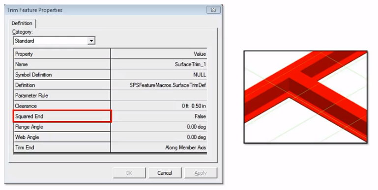
You can experiment with this command to see how it works. Pay attention to the Squared End property. If this property is set to True, then the member end is squared. If this property is set to False, then the member end trims exactly to your desired offset from the cutting surface.
您可以尝试使用此命令来了解其工作原理。注意**方形末端**属性。如果此属性设置为**True**,则构件末端为方形。如果此属性设置为 False,那么构件末端将精确修剪到与切割表面所需的偏移量。
Using Trimming Member Command Demonstration——【操作】用面修剪
使用修剪构件命令演示
This video demonstrates using the Trim Member command, which manually copes and snips member parts based on objects and planes that you specify.
此视频演示了如何使用“修剪构件”命令,该命令根据您指定的对象和平面手动处理和剪切构件部分。
Use this command when assembly connections are not sufficient to resolve the interference conflicts due to the position, orientation, and complexity of the intersecting members. You can place a trim and an assembly connection at the same member end.
当装配连接不足以解决由于相交构件的位置、方向和复杂性而产生的干扰冲突时,请使用此命令。您可以将修剪和装配连接放置在同一构件端。
However, the results of the trim might be overwritten by the assembly connection results making the trim redundant. Both the trim and the assembly connection are listed in the Workspace Explorer under the member part. The command works by first selecting the member you want to trim.
但是,修剪的结果可能会被装配连接结果覆盖,从而使修剪变得多余。修剪和装配连接都列在构件部分下的工作区资源管理器中。该命令的工作原理是首先选择要修剪的构件。
Then, selecting the trimming surface. Click Trim Member on the vertical toolbar. Select the member or members to trim.
然后,选择修剪表面。单击垂直工具栏上的“修剪构件”。选择要修剪的一个或多个构件。
Click Accept. Select the surface to trim to. Click Finish. You can continue to trim members as needed.
单击“接受”。选择要修剪到的表面。单击“完成”。您可以根据需要继续修剪构件。
Summary
总结
You've completed the course! In this course, you learned about placing assembly connections in a structure. Before you go, look at everything you learned. You now know how to:
您已完成课程!在本课程中,您学习了如何在结构中放置装配连接。在学习之前,请回顾一下您学到的所有内容。您现在知道如何:
- Use the Place Assembly Connection command.
- Use the Trim Member command.
- Edit the assembly connection properties.
-
Place and manipulate assembly connections in a structure.
-
使用 放置装配连接 命令。
- 使用 修剪构件 命令。
- 编辑装配连接属性。
- 在结构中放置和操作装配连接。
Fireproofing
防火
- Understand fireproofing specifications.
- Place fireproofing on an entire structure.
-
Place two types of fireproofing on a single member.
-
了解防火规范。
- 在整个结构上铺设防火材料。
- 在一个构件上铺设两种防火材料。
Introduction
简介
Fireproofing can be defined on setback distances from the member end.
防火措施可根据构件末端的后退距离进行定义。
Multi-segmented fireproofing can be applied along side a single member or to an entire model in a single operation.
多段防火措施可沿单个构件应用,也可在一次操作中应用于整个模型。
The command allows fireproofing to be applied on:
该命令允许将防火措施应用于:
- Columns
- Beams
- Horizontal braces
-
Vertical braces
-
柱
- 梁
- 水平支撑
- 垂直支撑
More About Fireproofing
有关防火的更多信息
This video provides an introduction to the Fireproofing features that can be place on your model's columns, beams, horizontal braces, and vertical braces member systems. You cannot place fireproofing on slabs, walls, plates, marine profiles, or surfaces.
本视频介绍了可放置在模型的柱、梁、水平支撑和垂直支撑构件系统上的防火功能。您不能将防火材料放置在板、墙、板、海洋型材或表面上。
You also cannot copy fireproofing directly from one member to another. However, fireproofing will copy and move with its parent member.
您也不能将防火材料直接从一个构件复制到另一个构件。但是,防火材料将随其父构件一起复制和移动。
Fireproofing is placed in the Insulation aspect, which is automatically turned on for you when fireproofing is placed.
防火材料放置在绝缘方面,放置防火材料时会自动为您打开。
You can use the Format, View command to turn the insulation display on and off in the model as needed.
您可以使用“格式”、“视图”命令根据需要在模型中打开和关闭绝缘显示。
You can define fireproofing setback distances from each member end, apply multi-segmented fireproofing along a single member, and apply fireproofing to the entire model in one operation while still maintaining placement rules for different member types. The material, grade, thickness, and rating of the fireproofing are controlled by the fireproofing specifications defined in the catalog. You can edit the fireproofing encasement rules in the catalog without any need for custom programming. Two encasement rules, Member Concrete and Member Fibrous, are delivered under the Structure, Objects, Insulation, Fireproofing node in the Catalog task.
您可以定义防火材料从每个构件末端的退让距离,沿单个构件应用多段防火材料,并在一次操作中将防火材料应用于整个模型,同时仍保持不同构件类型的放置规则。防火材料的材料、等级、厚度和评级由目录中定义的防火规格控制。您可以在目录中编辑防火包覆规则,而无需进行任何自定义编程。目录任务中的结构、对象、绝缘、防火节点下提供了两个包覆规则,即构件混凝土和构件纤维。
Fireproofing is specification-driven with user-modifiable encasement rules. Encasement rules can be applied to any cross-section, any member type, or any combination of cross-section and member type.
防火由规范驱动,具有用户可修改的包覆规则。包覆规则可应用于任何横截面、任何构件类型或横截面和构件类型的任何组合。
Sets of encasement rules can be driven by a fireproofing specification. Therefore, you can create specifications based on a particular project or a particular client. The standard encasement shapes (block, block-top exposed, contour, contour-top exposed, and round) are provided.
包覆规则集可由防火规范驱动。因此,您可以根据特定项目或特定客户创建规范。提供了标准包覆形状(块、块顶部暴露、轮廓、轮廓顶部暴露和圆形)。
You can define custom encasement shapes using the 2D Symbols editor. Fireproofing must be in the same permission group as the member it is placed on. Therefore, the software automatically maintains this relationship by changing the fireproofing permission group when you change the parent member permission group.
您可以使用 2D 符号编辑器定义自定义包覆形状。防火必须与其所在的构件位于同一权限组中。因此,当您更改父成员权限组时,软件会通过更改防火权限组来自动维护此关系。
Similarly, if you change the fireproofing permission group, the software automatically changes the member permission group to match.
同样,如果您更改防火权限组,软件会自动更改成员权限组以匹配。
A similar situation is maintained for the approval status. The member's approval status cannot be "less" than the fireproofing approval status.
对于批准状态,也保持类似的情况。成员的批准状态不能“低于”防火批准状态。
Setting the member to a lesser approval status (from Approved to In Review for example) will cause the fireproofing to be set to the same status.
将成员设置为较低的批准状态(例如从“已批准”更改为“正在审核”)将导致防火设置为相同的状态。
Similarly, increasing the fireproofing status increases the approval status of the member. Change the locate filter to Member Systems.
同样,增加防火状态会增加成员的批准状态。将定位过滤器更改为成员系统。
功能演示——防火层的功能按钮
Click Place Fireproofing on the vertical toolbar to open the fireproofing ribbon. Let's review the ribbon controls. Select is activated automatically by the software so that you can select the members on which you want to place fireproofing. By Rule allows the software to select the fireproofing to use based on the selected member and the encasement rules defined in the catalog. Clear this option to select the encasement type yourself.
单击垂直工具栏上的“放置防火”以打开防火功能区。让我们查看功能区控件。选择由软件自动激活,以便您可以选择要放置防火的成员。按规则允许软件根据所选成员和目录中定义的封装规则选择要使用的防火。清除此选项可自行选择封装类型。
Condition specifies how you want the software to handle existing fireproofing when you try to place a new fireproofing on the same member.
条件指定当您尝试在同一成员上放置新的防火时,您希望软件如何处理现有防火。
Select Retain to keep the existing fireproofing. Select Add to add additional fireproofing to a member that already has fireproofing. Select the insulation specification that you want to use. Select the encasement that you want to use from the Catalog.
选择“保留”以保留现有的防火措施。选择“添加”以向已有防火措施的构件添加额外的防火措施。选择要使用的绝缘规格。从目录中选择要使用的外壳。
Available encasements depend on the insulation specification that you have selected. If you select the By Rule option, then the encasement option is not available because the Encasement item is selected by the encasement rule. Reference 1 and Reference 2 will allow choosing Part Start, Part End, Axis Start, and Axis End. You can set the distance in the Distance 1 and Distance 2 boxes when the By Rule option is cleared. These distance values are instrumental in applying multiple fireproofing on a single member.
可用的外壳取决于您选择的绝缘规格。如果选择“按规则”选项,则外壳选项不可用,因为外壳项目是由外壳规则选择的。参考 1 和参考 2 将允许选择零件起点、零件终点、轴起点和轴终点。当“按规则”选项被清除时,您可以在距离 1 和距离 2 框中设置距离。这些距离值有助于在单个构件上应用多重防火措施。
Select the members to apply fireproofing. Click Accept. Click Finish.
选择要应用防火措施的构件。单击“接受”。单击“完成”。
Place Fireproofing on Dissimilar Member Types——【操作】根据类型不同设置不同的防火层
将防火材料放置在不同类型的构件上
Let's now see the procedure for placing fireproofing on dissimilar member types.
现在让我们看看将防火材料放置在不同类型的构件上的程序。
【操作】
This video demonstrates the procedure for placing fireproofing on dissimilar Member Types. Select the Place Fireproofing command
该视频演示了在不同构件类型上放置防火材料的过程。选择放置防火材料命令
Select a Column, Beam, and Brace in the model. Clear the By Rule option. In the Encasement box, select More.
在模型中选择柱、梁和支撑。清除按规则选项。在包层框中,选择更多。
Select Column_Contour_Encased_All_Conc. Click OK. Click Accept. A warning box appears because we are trying to place a column encasement on a beam and brace.
选择 Column_Contour_Encased_All_Conc。单击确定。单击接受。出现警告框,因为我们正尝试在梁和支撑上放置柱包层。
Click OK to close message. Click Finish. Fireproofing is applied only to the column, but the selection is retained.
单击确定关闭消息。单击完成。防火仅适用于柱,但选择保留。
In Encasement, select Beam_Contour_Exposed_All_Conc, and click OK. Click Accept. A warning message appears because we are trying to place a beam encasement on a column and a brace. Click OK to close the warning. Click Finish. Fireproofing is applied to the beam only.
在包层中,选择 Beam_Contour_Exposed_All_Conc,然后单击确定。单击接受。出现警告消息,因为我们正尝试在柱和支撑上放置梁包层。单击确定关闭警告。单击完成。防火仅适用于梁。
Repeat the same steps to place Brace_Contour_Encased_All_Conc for
重复相同步骤放置 Brace_Contour_Encased_All_Conc
Modify Fireproofing Properties
修改防火属性
You can modify fireproofing properties by setting the Locate Filter to Insulation.
您可以通过将定位过滤器设置为绝缘来修改防火属性。
Modify Fireproofing and Place Multiple Fireproofing on a Single Member——【操作】放置多个防火层,设置缩进
修改防火措施并在单个构件上放置多个防火措施
This video demonstrates how to modify fireproofing, and then place multiple fireproofing on a single member. Change the locate filter to Insulation.
此视频演示了如何修改防火措施,然后在单个构件上放置多个防火措施。将定位过滤器更改为绝缘。
Select the insulation on the column. Verify that Reference 2 is set to Part End. Type 15 feet in the setback Distance 2 box.
选择柱上的绝缘。确认参考 2 设置为部件末端。在缩进距离 2 框中输入 15 英尺。
Notice that the existing insulation changes on the column. Click Place Fireproofing on the vertical toolbar. Change the Insulation Spec to Spray_1hr.
请注意,柱上的现有绝缘发生了变化。单击垂直工具栏上的放置防火措施。将绝缘规格更改为 Spray_1hr。
Select More in the Encasement list. Select Column_Contour_Encasement_All_ Fibr. Click OK. Select the column. Click Accept, and then click Finish
在包层列表中选择更多。选择 Column_Contour_Encasement_All_ Fibr。单击确定。选择柱。单击接受,然后单击完成
Click Select on the vertical toolbar, and then select the insulation you placed. Select Part Start for Reference 1.
单击垂直工具栏上的选择,然后选择您放置的绝缘。选择参考 1 的部件起点。
Enter 15 feet in Distance 1. This tells the system that you want the fireproofing to start 15 feet from the start of the column. Select Part End for Reference 2. Enter 3 feet in Distance 2.
在距离 1 中输入 15 英尺。这告诉系统您希望防火措施从柱的起点开始 15 英尺。选择参考 2 的部件末端。在距离 2 中输入 3 英尺。
This tells the system that you want the fireproofing to end 3 feet from the end of the column.
这告诉系统您希望防火措施在距柱末端 3 英尺处结束。
Note that the column now has two types of fireproofing applied.
请注意,该柱现在应用了两种类型的防火措施。
Retain Fireproofing
保留防火措施
You can keep existing fireproofing on a member when placing new fireproofing by changing the Condition option to Retain.
在放置新的防火措施时,您可以通过将“条件”选项更改为“保留”来保留构件上的现有防火措施。
Using the Retain Fireproofing Option——【操作】保留防火层
使用保留防火选项
This video demonstrates using the Retain option to prevent overwriting existing fireproofing. Select Place Fireproofing. Change Condition to Retain.
此视频演示了如何使用保留选项来防止覆盖现有的防火措施。选择放置防火材料。将条件更改为保留。
Select Insulation Spec as Conc_1hr. Select the By Rule option. Select several beams, including a beam that already has fireproofing.
选择绝缘规格为 Conc_1hr。选择按规则选项。选择多个梁,包括已经具有防火性能的梁。
Click Accept. A warning appears. Click OK to dismiss the warning. Click Finish. Fireproofing is retained on the existing beam and applied on the other beams.
单击接受。出现警告。单击确定以消除警告。单击完成。防火措施保留在现有梁上,并应用于其他梁。
Placing Fireproofing on Entire Structure
在整个结构上放置防火材料
This video demonstrates placing fireproofing on an entire structure in one operation. Set the locate filter to Member Systems.
此视频演示了如何通过一次操作在整个结构上放置防火材料。将定位过滤器设置为成员系统。
Select Place Fireproofing. Set the locate filter to Member Systems. Set Condition to Add. Select the By Rule option so the software will select the fireproofing based on the rules defined in the Catalog. Select Conc 1 hour for the Insulation Specification. Drag a fence around the entire structure.
选择放置防火材料。将定位过滤器设置为成员系统。将条件设置为添加。选择按规则选项,以便软件根据目录中定义的规则选择防火材料。选择 Conc 1 小时作为绝缘规范。在整个结构周围拖出一个围栏。
Click Accept. Click Finish to apply the fireproofing to the entire
单击接受。单击完成以将防火材料应用于整个结构
---Day2---
---Day3---
Place Slabs
放置板
- Place a slab using the 3 Points Plane Method and by Drawing 2D Boundaries.
- Place a slab by drawing the slab's boundaries in the 3D environment.
- Describe the slab entities and their relationships.
- Place a slab using the Coincident plane method.
- Place a slab using the Offset from Plane method.
-
Place a slab using the angle to plane option.
-
使用 3 点平面法和绘制 2D 边界来放置板坯。
- 通过在 3D 环境中绘制板坯的边界来放置板坯。
- 描述板坯实体及其关系。
- 使用重合平面法放置板坯。
- 使用平面偏移法放置板坯。
- 使用与平面成角度选项放置板坯。
The Place Slab Command
放置板命令
You place slabs in the model by selecting a support plane and then defining the slab’s boundaries by either picking model objects, sketching the boundaries in 2-D, or by sketching the boundaries in 3-D.
通过选择支撑平面,然后通过拾取模型对象、在二维中绘制边界或在三维中绘制边界来定义板的边界,即可在模型中放置板。
The Place Slab command allows you to model any type of planar, constant-thickness solid object such as:
“放置板”命令允许您对任何类型的平面、恒定厚度的实体对象进行建模,例如:
- Actual floor slabs
- Steel grating
- Steel plate
-
Roofing
-
实际楼板
- 钢格栅
- 钢板
- 屋顶
The Slab Properties
板坯属性
The slab properties define the type of solid object that you place by using the Place Slab command. The properties are used in your material reports. Your Catalog administrator can define the different types of slabs available for placement including specific properties associated with those types.
板坯属性定义您使用“放置板坯”命令放置的实体对象的类型。这些属性用于您的材料报告。您的目录管理员可以定义可供放置的不同类型的板坯,包括与这些类型相关的特定属性。
Defining a plane for the slab relative to other objects in the model.
定义板坯相对于模型中其他对象的平面。
Defining the boundary of the slab with optional relationships to other objects in the model.
定义板坯的边界,并可选择与模型中其他对象的关系。
Methods of Defining the Location of Slab Plane
定义板平面位置的方法
A common activity while working with slabs is defining planes. These planes are used to define the location of the slab or as a sketching plane for the slab boundaries.
处理板时,一个常见的活动是定义平面。这些平面用于定义板的位置或作为板边界的草绘平面。
Coincident: Defines a plane coincident to another plane. Use this method when you want the slab to remain coincident with another plane. For example, you can use this method to place a slab to remain coincident with an elevation plane of your grid system.
重合:定义与另一个平面重合的平面。当您希望板与另一个平面保持重合时,请使用此方法。例如,您可以使用此方法将板放置为与网格系统的高程平面保持重合。
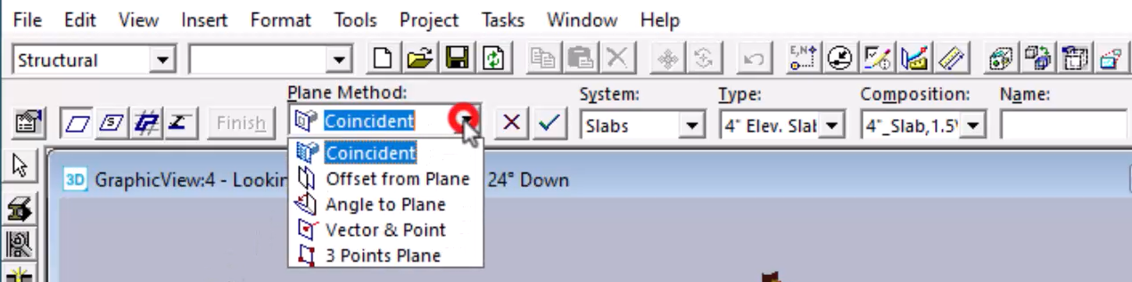
Offset from Plane: Defines a plane at a specified offset distance from another plane. Use this method when you want the slab to remain at a given offset from another plane. For example, you can use this method to place a slab to remain 4 ft above the second storey elevation plane.
与平面的偏移: 定义与另一个平面具有指定偏移距离的平面。当您希望板坯与另一个平面保持给定偏移时,请使用此方法。例如,您可以使用此方法将板坯放置在高于二楼高程平面 4 英尺的位置。
3 Points Plane: Defines a plane using three points. Use this method when you just want to position the slab at a specific location in space or relative to specific points along existing design objects.
3 点平面:使用三个点定义一个平面。当您只想将板坯定位在空间中的特定位置或相对于现有设计对象上的特定点时,请使用此方法。
Vector & Point: Defines a plane by using two points to define the normal vector for the plane and a third point to define the plane position along the vector. Use this method when you need to orient the surface normal to a vector you know. This is useful in cases where you use the Place Slab command to model complex steel plate structures.
矢量和点:使用两个点定义平面的法向量,使用第三个点定义平面沿向量的位置,从而定义平面。当您需要将表面法线定向到您知道的向量时,请使用此方法。当您使用“放置板”命令对复杂钢板结构进行建模时,这很有用。
Angle to Plane: Defines a plane at a specified angle or slope to another plane. Use this method when you need to place a sloped slab. For example, you can use this method to place a sloped slab with reference to the ground elevation plane and at any elevation.
与平面的角度:定义与另一个平面成指定角度或斜度的平面。当您需要放置倾斜板时使用此方法。例如,您可以使用此方法参考地面高程平面和任意高程放置倾斜板。
Demonstration—Placing a Slab by Using Coincident Plane Method——【操作】边界定义板
演示 — 使用重合平面法放置板
This video demonstrates placing a slab on the first floor of Unit U03 by using the Coincident plane method and selecting boundary objects. How to solve ambiguous boundary selections will also be shown. Use the Clip by Object command to clip the view to only display the first floor beams.
此视频演示了如何使用重合平面法和选择边界对象在 U03 单元的一楼放置板。还将展示如何解决模糊的边界选择。使用“按对象剪辑”命令剪辑视图以仅显示一楼梁。
Click Place Slab on the vertical toolbar. On the ribbon, set Plane Method to Coincident. For System, select A2, U03, Structural, Slabs.
单击垂直工具栏上的“放置板”。在功能区上,将平面方法设置为重合。对于系统,选择 A2、U03、结构、板。
In the Type list, select 4 Elevated slab - Composite. For Composition, select 4_Slab, 1.5VL22. Set Face Position to Bottom.
在类型列表中,选择 4 高架板 - 复合。对于组合,选择 4_Slab、1.5VL22。将面位置设置为底部。
In the Workspace Explorer, select the 18 foot elevation plane as the slab's support plane. Click Accept on the ribbon.
在工作区资源管理器中,选择 18 英尺高程平面作为板的支撑平面。单击功能区上的“接受”。
You are prompted to select the slab's boundaries. Select the beams on the first floor. For best results, select the boundaries in clockwise order, selecting only one object per slab edge. Click Accept to indicate you are finished selecting boundaries.
系统会提示您选择板的边界。选择一楼的梁。为获得最佳效果,请按顺时针顺序选择边界,每个板边缘仅选择一个对象。单击“接受”表示您已完成选择边界。
At this point, the system indicates that there are ambiguous boundaries defined and multiple solutions exist to create the slab. Move the cursor over the areas where you want to place the slab.
此时,系统指示定义的边界不明确,并且存在多个创建板的解决方案。将光标移到要放置板的区域上。
The possible boundary solutions highlight. Point and click to select the areas that should comprise your slab. Click Finish to place the slab.
可能的边界解决方案突出显示。指向并单击以选择应组成板的区域。单击“完成”以放置板。
Demonstration—Placing a Slab by Using Offset from a Plane Method——【操作】偏移板
演示 — 使用平面偏移方法放置板
This video demonstrates creating a slab using the Offset from a Plane method. How to define boundary offsets will also be shown.
此视频演示了如何使用平面偏移方法创建板。还将展示如何定义边界偏移。
Using the Clip by Object command, isolate the beams on the roof elevation.
使用“按对象剪辑”命令,隔离屋顶高程上的梁。
Click Place Slab on the vertical toolbar. Select Offset from Plane from the Plane Method list. Type minus 2 feet for the Offset value.
单击垂直工具栏上的“放置板”。从“平面方法”列表中选择“平面偏移”。输入“偏移”值减 2 英尺。
In the Workspace Explorer, select the 44 foot elevation plane. Click Accept. Select Roof Deck for the slab type.
在工作区资源管理器中,选择 44 英尺高程平面。单击“接受”。选择“屋顶板”作为板类型。
Select RD_1.5B24 from the Composition list. Set Face Position to Bottom. Set the System to A2, U03, Structural, Slabs.
从“组合”列表中选择“RD_1.5B24”。将“面位置”设置为“底部”。将“系统”设置为“A2、U03、结构、板”。
Select the slab boundaries. For best results, select the boundaries in a clockwise order.
选择板边界。为获得最佳效果,请按顺时针顺序选择边界。
Select the Boundaries Offset option. In the dialog, set the offset for Grid Lines 1 and 3 to 1 foot.
选择“边界偏移”选项。在对话框中,将网格线 1 和 3 的偏移设置为 1 英尺。
Set the offset for Grid Lines 2 and 4 to 2 feet. Click OK. Click Finish to place the slab.
将网格线 2 和 4 的偏移设置为 2 英尺。单击“确定”。单击“完成”以放置板。
Demonstration—Placing a Slab by Using 3 Points Plane Method and Drawing 2D Boundaries——【操作】2D绘制
演示 — 使用 3 点平面法放置板并绘制 2D 边界
This video demonstrates placing a slab using the 3 Points Plane Method and by Drawing 2D Boundaries. Using Clip by Object to clip the model to where you want to place a slab.
此视频演示了如何使用 3 点平面法和绘制 2D 边界来放置板。使用“按对象剪辑”将模型剪辑到要放置板的位置。
Click Place Slab on the vertical toolbar. On the ribbon, set Plane Method to 3 Points Plane. Set System to A2, U03, Structural, Slabs.
单击垂直工具栏上的“放置板”。在功能区上,将“平面法”设置为“3 点平面”。将“系统”设置为“A2、U03、结构、板”。
Set the Type to 4 Elevated Slab - Composite. Set Composition to 4_Slab, 1.5VL22. Finally, set Face Position to Bottom.
将“类型”设置为“4 高架板 - 复合”。将“组合”设置为“4_板,1.5VL22”。最后,将“面位置”设置为“底部”。
The software prompts you to select the points to define the plane's location and orientation. In the graphic view, select the three points for the plane.
软件会提示您选择点来定义平面的位置和方向。在图形视图中,选择平面的三个点。
Click "Add References to Sketch 2D" to select which objects in the 3D environment to see in the sketch 2-D environment when you are drawing the slab boundaries. The objects that you select display as thick blue lines in the 2-D environment.
单击“添加对 2D 草图的引用”以选择绘制板边界时要在 2D 草图环境中查看 3D 环境中的哪些对象。您选择的对象在 2-D 环境中显示为粗蓝线。
You can define relationships and dimensions to these blue-lined objects in 2-D. The software might also automatically retrieve 3-D objects to display in the 2-D environment. The automatically selected objects will display as grey lines. These grey line objects are read-only (you cannot define relationships or dimensions to them) and are there to help you visualize the model. Select the four beams and the two columns as referenced objects.
您可以在 2-D 中定义这些蓝线对象的关系和尺寸。软件还可能自动检索 3-D 对象以在 2-D 环境中显示。自动选择的对象将显示为灰线。这些灰线对象是只读的(您无法定义它们的关系或尺寸),可帮助您可视化模型。选择四根梁和两根柱子作为参考对象。
Click Draw on the ribbon to open the Draft 2D View window. Draw the boundaries for the slab.
单击功能区上的“绘制”以打开“草图 2D 视图”窗口。绘制板的边界。
Make sure that you draw a closed shape. When you are finished, click Close to return to the 3D environment.
确保绘制一个封闭的形状。完成后,单击“关闭”返回 3D 环境。
Click Accept and then click Finish to place the slab.
单击“接受”,然后单击“完成”以放置板。
Demonstration—Placing a Slab by Using Coincident Plane Method and Drawing 3D Boundaries——【操作】3D绘制
演示 — 使用重合平面法放置板并绘制 3D 边界
This video demonstrates placing a slab by the drawing the slab's boundaries in the 3D environment. Using Clip by Object, isolate the beams at the 31 foot elevation.
此视频演示了如何在 3D 环境中绘制板的边界来放置板。使用“按对象裁剪”,将梁隔离在 31 英尺高程处。
Click Place Slab on the vertical toolbar. Set Plane Method to Coincident. In the Workspace Explorer, select the 31 foot elevation plane.
单击垂直工具栏上的“放置板”。将平面法设置为“重合”。在工作区资源管理器中,选择 31 英尺高程平面。
Click Accept on the ribbon. Set System to A2, U03, Structural, Slabs. Set Type to 4 inch Elevation Slab Composite.
单击功能区上的“接受”。将“系统”设置为“A2、U03、结构、板”。将“类型”设置为“4 英寸高程板复合材料”。
Set Composition to 4 inch Slab 1.5VL22. Set Face Position to Bottom. Click Sketch 3D on the Place Slab ribbon.
将“组合”设置为“4 英寸板 1.5VL22”。将“面位置”设置为“底部”。单击“放置板”功能区上的“草图 3D”。
Sketch the slab boundaries.
绘制板边界。
You must define a closed shape for your slab's boundaries. If needed, you can edit the sketched boundaries after the slab has been placed. Click Finish on the 3D Sketch ribbon. Click Finish on the Place Slab ribbon.
您必须为板的边界定义一个封闭的形状。如果需要,您可以在放置板后编辑绘制的边界。单击 3D 草图功能区上的“完成”。单击“放置板”功能区上的“完成”。
Demonstration—Placing a Slab by Using Angled to Plane Method——【操作】
演示 — 使用与平面成角度的方法放置板坯
You can define a plane at a specified angle or slope to another plane. You must define an axis of rotation and the angle or slope.
您可以定义一个平面与另一个平面成指定角度或斜率。您必须定义旋转轴和角度或斜率。
The video demonstrates placing a slab using the angle to plane option. Click Place Slab on the vertical toolbar.
视频演示了如何使用与平面成角度选项放置板坯。单击垂直工具栏上的“放置板坯”。
On the ribbon, set Plane Method to Angle to Plane. Set System to A2, U03, Structural, Slab. Type to 4 inch Cast in Place.
在功能区上,将“平面方法”设置为“与平面成角度”。将“系统”设置为“A2、U03、结构、板坯”。将“类型”设置为“4 英寸现场浇筑”。
Set Composition to CIP 4 Fc3 and Face Position to Top.
将“构图”设置为“CIP 4 Fc3”,将“面位置”设置为“顶部”。
Select the elevation plane at 0 feet. When using the angle to plane method, you have to define a rotation axis. Select either end of the grid line to define the rotation axis. Set the slope to 10%.
选择 0 英尺处的高程平面。使用与平面成角度的方法时,您必须定义旋转轴。选择网格线的任一端以定义旋转轴。将斜率设置为 10%。
Select the four grid lines as the slab boundaries. Click Accept to confirm the boundaries. Click Finish to place the slab.
选择四条网格线作为板坯边界。单击“接受”以确认边界。单击“完成”以放置板坯。
Summary
总结
On the next page, review the different methods used to define a plane while working with slabs.
在下一页中,回顾使用板时定义平面的不同方法。
In this course, you learned about the Place Slab command that places a slab in a 3D model.
在本课程中,您学习了将板放置在 3D 模型中的“放置板”命令。
Slabs are used to model solid surfaces, such as floors or steel grating, in your 3D model.
板用于在 3D 模型中对实体表面(例如地板或钢格栅)进行建模。
Smart 3D places slabs on a supporting plane, or multiple planes, that you select and between selected boundaries. The supporting plane of the slab can be an elevation plane, a grid plane, the surface of a Smart Interop Object, or a plane that you define during placement. You can define planes at an angle to an existing elevation or grid plane, or you can define a plane in space using three points.
Smart 3D 将板放置在您选择的一个或多个支撑平面上,并放置在选定的边界之间。板的支撑平面可以是立面平面、网格平面、Smart Interop 对象的表面或您在放置过程中定义的平面。您可以定义与现有立面或网格平面成一定角度的平面,也可以使用三个点在空间中定义平面。
Place Walls
放置墙壁
Introduction
简介
A wall system design consist of the elements listed in the illustration.
墙壁系统设计由图中列出的元素组成。
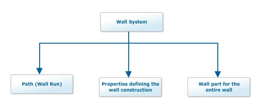
Walls Introduction——讲解
墙体简介
In this course, you will learn how to place walls in a model by using the Place Wall command.
在本课程中,您将学习如何使用“放置墙体”命令在模型中放置墙体。
The solid 3D geometry of walls is modeled by defining a path on a plane, the cross-section size, and optionally, selecting the graphic boundaries to trim the top of the wall. You choose the positioning of the cross-section relative to the path by cardinal points defined on the cross-section shape. The wall properties define the layered composition of the wall.
通过在平面上定义路径、横截面尺寸以及(可选)选择图形边界来修剪墙体的顶部,可以对墙体的实体 3D 几何图形进行建模。您可以通过横截面形状上定义的基点来选择横截面相对于路径的位置。墙体属性定义墙体的分层构成。
A wall system consists of a path (also called a wall run), a set of properties defining the wall construction, and a wall part for the entire wall run. This design allows for the ability to split a wall into multiple parts for detailed panel modeling. This design is similar to the concept of splitting a member system.
墙体系统由路径(也称为墙体运行)、定义墙体构造的一组属性以及整个墙体运行的墙体部分组成。此设计允许将墙体拆分为多个部分以进行详细的面板建模。此设计类似于拆分构件系统的概念。
Because a wall system must have the same thickness along the wall run, you must create separate wall systems to have walls with different thickness properties.
由于墙体系统沿墙体运行必须具有相同的厚度,因此您必须创建单独的墙体系统以使墙体具有不同的厚度属性。
You can connect one wall system to another. At the connection point, the wall geometry is automatically trimmed to represent the corner or tee properties. You can also split a wall system into multiple wall systems, if you need to make changes to a portion of the original wall system after initial modeling. The Catalog contains the wall cross-section shapes, material, and construction parts that you can place in the structure. The Catalog administrator can customize the Catalog wall definitions.
您可以将一个墙体系统连接到另一个墙体系统。在连接点处,墙体几何图形会自动修剪以表示角或 T 形属性。如果您需要在初始建模后对原始墙体系统的一部分进行更改,也可以将一个墙体系统拆分为多个墙体系统。目录包含您可以放置在结构中的墙体横截面形状、材料和建筑部件。目录管理员可以自定义目录墙体定义。
The supporting plane of the wall can be an elevation plane, the surface of a slab, or any other planar surface in the model.
墙体的支撑平面可以是立面、板的表面或模型中的任何其他平面。
You can define the path of the wall using the 3D Sketch or 2D Sketch methods. The 3D Sketch method allows you to directly reference 3D model design objects while drawing the path. The 2D Sketch method requires you to specifically select the design objects you want to reference within the Sketch 2D drawing environment.
您可以使用 3D 草图或 2D 草图方法定义墙体的路径。3D 草图方法允许您在绘制路径时直接引用 3D 模型设计对象。2D 草图方法要求您在草图 2D 绘图环境中专门选择要引用的设计对象。
The Sketch 2D drawing environment gives you more drawing functionalities including the ability to define dimensions that automatically adjust the wall size.
草图 2D 绘图环境为您提供了更多绘图功能,包括定义自动调整墙体尺寸的尺寸的能力。
In both the sketching methods, you can efficiently create multiple wall systems as you define the wall run, without exiting the Place Wall command. You can then edit the thickness or other construction properties of the different wall systems you have defined.
在这两种草图方法中,您都可以在定义墙体运行时高效地创建多个墙体系统,而无需退出“放置墙体”命令。然后,您可以编辑已定义的不同墙体系统的厚度或其他构造属性。
You can later split these wall systems into multiple wall systems if you need to change the properties of a portion of the existing wall system. For example, if you want to edit the thickness of one of the walls in a wall system, you can split the wall system into multiple wall systems and then change the thickness of one of the walls.
如果您需要更改现有墙体系统的一部分的属性,则可以稍后将这些墙体系统拆分为多个墙体系统。例如,如果您要编辑墙体系统中一面墙的厚度,则可以将墙体系统拆分为多个墙体系统,然后更改其中一面墙的厚度。
You can place doors and windows in the wall and cut arbitrary openings by using the Place Opening command.
您可以使用“放置开口”命令在墙上放置门窗并切割任意开口。
In addition, you can get reports of the wall's surface area with or without the openings.
此外,您可以获得有开口或无开口的墙体表面积报告。
Placing Walls by Using Sketch 3D——【操作】3D绘制
使用 Sketch 3D 放置墙
This video demonstrates placing an exterior bearing wall using the 3D Sketch method. Select Place Wall on the vertical toolbar.
此视频演示了如何使用 3D Sketch 方法放置外承重墙。在垂直工具栏上选择“放置墙”。
On the ribbon, set System to A2, U05, Structural, Walls. Select Exterior Bearing Wall Composite for the Type.
在功能区上,将系统设置为 A2、U05、结构、墙。选择“外承重墙复合材料”作为类型。
Set Composition to EBW Brick 5 inch Air 4 inch Bath and Roll 2 inch Siding Vinyl 0.046 inch.
将成分设置为 EBW 砖 5 英寸空气 4 英寸浴缸和卷材 2 英寸壁板乙烯基 0.046 英寸。
Set Position to 3 Bottom Right. The Total Thickness as 9 inches. Set the Maximum Height to 15 feet.
将位置设置为 3 右下角。总厚度为 9 英寸。将最大高度设置为 15 英尺。
Select the slab's top surface for the sketching plane. On the Place Wall ribbon, select Sketch 3D option.
选择板的顶面作为绘制平面。在“放置墙”功能区上,选择“草图 3D”选项。
Sketch the boundaries of the wall.
绘制墙的边界。
Select the Path Type as Arc By 3 Points option, and continue defining the wall path around the slab's curve.
选择“路径类型”为“3 点弧”选项,然后继续定义板曲线周围的墙路径。
Select Finish on the Sketch 3D ribbon to return to the Place Wall ribbon. Select Finish to place the wall part in the model.
在“草图 3D”功能区上选择“完成”以返回“放置墙”功能区。选择“完成”以将墙部件放置在模型中。
The command restarts after you select Finish, defaulting the sketching surface to the last selected surface, and the sketching method to the last selected sketching method, which in this case is 3D. Sketch the path for the divider wall. Select Finish on the Sketch 3D ribbon.
选择“完成”后,命令将重新启动,默认将绘制表面设置为最后选定的表面,将绘制方法设置为最后选定的绘制方法(在本例中为 3D)。绘制分隔墙的路径。在“草图 3D”功能区上选择“完成”。
The system returns to the Place Wall ribbon and displays the divider wall in dynamics mode. Select Finish to place the wall.
系统将返回“放置墙”功能区并以动态模式显示分隔墙。选择“完成”放置墙。
A 3D-sketched wall system can only be split at corners. Therefore, it is better to design complex room layouts using the 2D Sketch method. Not only is the editing behavior at connections among the wall systems better, but you also have powerful dimensioning and sketching tools that are not available in the 3D Sketch tool.
3D 绘制的墙系统只能在角落处分割。因此,最好使用 2D 草图方法设计复杂的房间布局。不仅墙系统连接处的编辑行为更好,而且您还拥有 3D 草图工具中没有的强大尺寸标注和绘制工具。
Use the 3D Sketch method for simple wall layouts.
使用 3D 草图方法进行简单的墙布局。
Placing Walls by Using Sketch 2D——【操作】2D放置墙
使用 Sketch 2D 放置墙
This video demonstrates placing an exterior bearing wall using the 2D Sketch method. Select Place Wall on the vertical toolbar.
此视频演示了如何使用 2D Sketch 方法放置外承重墙。在垂直工具栏上选择“放置墙”。
On the ribbon, set System to A2, U05, Structural, Walls. Select Exterior Bearing Wall Composite for the Type.
在功能区上,将“系统”设置为“A2、U05、结构、墙”。选择“外承重墙复合材料”作为类型。
Set Composition to EBW Brick 5 inch Air 4 inch Bath and Roll 2 inch Siding Vinyl 0.046 inch.
将“组合”设置为“EBW 砖 5 英寸空气 4 英寸浴缸和卷材 2 英寸壁板乙烯基 0.046 英寸”。
Set Position to 3 Bottom Right. The Total Thickness as 9 inches. Set the Maximum Height to 15 feet.
将“位置”设置为“右下角 3”。总厚度为 9 英寸。将“最大高度”设置为 15 英尺。
Select the slab's top surface for the sketching plane. Select the Sketch 2D option. The Add References to Sketch 2D option is selected by default.
选择板的顶面作为绘制平面。选择“Sketch 2D”选项。默认情况下,“添加对 Sketch 2D 的引用”选项处于选中状态。
Select the objects in the model that you want to see while sketching the wall run in the 2D environment.
选择模型中您想要在 2D 环境中绘制墙板时看到的对象。
Select Draw to sketch the wall run in the Draft 2D View. Sketch the straight line part of the wall run.
选择“绘制”以在“草图 2D 视图”中绘制墙板。绘制墙板的直线部分。
As you sketch the path, be sure to create the SmartSketch relationships to the referenced slab plane. Swipe past elements to add them to the SmartSketch list, and therefore make them available for relationships.
在绘制路径时,请确保创建与参考板平面的 SmartSketch 关系。滑动元素以将它们添加到 SmartSketch 列表中,从而使它们可用于关系。
Change to the Arc By 3 Points option, and finish defining the wall run around the curve in the slab.
更改为“3 点弧”选项,并完成定义板中曲线周围的墙。
Switch back to the straight line, select the starting point of the divider wall, and sketch the path for the divider wall.
切换回直线,选择分隔墙的起点,并绘制分隔墙的路径。
Select Close to return to the 3D environment. Select Finish on the Sketch 2D ribbon to return to the Place Wall ribbon.
选择“关闭”返回 3D 环境。选择“草图 2D”功能区上的“完成”返回“放置墙”功能区。
Select Finish to place the walls in the model.
选择“完成”将墙放置在模型中。
Splitting a Wall System Using Sketch 2D——【操作】2D拆分墙系统
使用 Sketch 2D 拆分墙系统
This video demonstrates how you split a wall system that was created using a 2D sketched path. Set the Locate Filter to Wall Systems.
此视频演示了如何拆分使用 2D 草图路径创建的墙系统。将“定位过滤器”设置为“墙系统”。
Select the wall system created by the single 2D Sketch. On the edit ribbon, click the "Select a Path" smartstep, and then select the Sketch 2D option. Click Draw on the Sketch 2D ribbon. Select View, Toolbars
选择由单个 2D 草图创建的墙系统。在编辑功能区上,单击“选择路径”智能步骤,然后选择“草图 2D”选项。单击“草图 2D”功能区上的“绘制”。选择“视图”、“工具栏”
Activate the Change toolbar and select okay. On the Change toolbar, select the "Split group at connection points"最后一个按钮 command.
激活“更改”工具栏并选择“确定”。在“更改”工具栏上,选择“在连接点处拆分组”命令。
Select the connection points where you want to split the wall into multiple wall systems.
选择要将墙拆分为多个墙系统的连接点。
Select Split. Select Close and then select Finish to return to the Place Wall ribbon. Click Finish on the Place Wall ribbon.
选择“拆分”。选择“关闭”,然后选择“完成”以返回“放置墙”功能区。单击“放置墙”功能区上的“完成”。
Notice that there are now multiple wall systems. In the Sketch 2D environment, the multiple connected segments that form individual wall systems are assigned to separate groups. Select the top-down selection option to see the groupings highlight. After splitting a wall system into two, you can combine the two wall systems into a single wall system again by using the Modify Group command.
请注意,现在有多个墙系统。在 Sketch 2D 环境中,形成单个墙系统的多个连接段被分配到单独的组。选择自上而下选择选项以查看突出显示的分组。将墙体系统拆分为两个后,可以使用“修改组”命令将两个墙体系统再次合并为一个墙体系统。
This command allows you to add elements to an existing group. All elements in a group become a wall system.
此命令允许您将元素添加到现有组。组中的所有元素都将成为墙体系统。
Do not use the Group and Ungroup commands in the Sketch 2D environment while defining walls. Using these commands removes the identifications used to associate the wall systems with the groups in the 2D Sketch.
定义墙体时,请勿在草图 2D 环境中使用“分组”和“取消分组”命令。使用这些命令会删除用于将墙体系统与 2D 草图中的组相关联的标识。
Splitting a Wall System Using Sketch 3D——【操作】3D拆分墙
使用 Sketch 3D 拆分墙系统
This video demonstrates how to split a wall system using Sketch 3D. Set the Locate Filter to Wall Systems and hover your cursor over the exterior wall. Notice that it is a single wall system. Select the exterior wall.
此视频演示了如何使用 Sketch 3D 拆分墙系统。将“定位过滤器”设置为“墙系统”,然后将光标悬停在外墙上。请注意,这是一个单墙系统。选择外墙。
Select the "Select a Path" smartstep from the ribbon. Select the Sketch 3-D icon. Notice you can choose the path anywhere along the wall run.
从功能区中选择“选择路径”智能步骤。选择 Sketch 3-D 图标。请注意,您可以选择沿墙运行的任何路径。
However, wall systems can only be split at turns. Zoom into a wall corner, and select the small yellow box that indicates the path turn. In the ribbon, set Turn Type to Split. Select the next corner's box in the path and change its Turn Type to Split.
但是,墙系统只能在转弯处拆分。放大墙角,然后选择指示路径转弯的小黄色框。在功能区中,将“转弯类型”设置为“拆分”。选择路径中下一个角落的框,并将其“转弯类型”更改为“拆分”。
Select Finish. The software splits the wall system at the points you specified. Now, select Finish again to create the new wall system.
选择“完成”。软件会在您指定的点处拆分墙系统。现在,再次选择“完成”以创建新的墙系统。
Move your cursor over to highlight the now, two wall systems.
将光标移到上方以突出显示现在的两个墙系统。
Editing Walls Overview
编辑墙体概述
You can edit different wall systems created from one 2D Sketch to have different thickness or other wall properties.
您可以编辑从一个 2D 草图创建的不同墙体系统,使其具有不同的厚度或其他墙体属性。
When a sketch line segment either has no relationship to another segment in the sketch, or if the connection is a T as in the interior wall, then a separate wall system is automatically created for the connected set of segments. You can see this by selecting the walls in the 3D graphic window.
当草图线段与草图中的另一个线段没有关系,或者连接是 T 形(如内墙)时,将自动为连接的线段集创建单独的墙体系统。您可以通过在 3D 图形窗口中选择墙体来查看这一点。
You can edit the wall systems to have different thickness or other wall properties. When you edit the path of any of the wall systems created by using the 2D Sketch method, you will see the single sketch and will be able to edit the path of all the wall systems.
您可以编辑墙体系统,使其具有不同的厚度或其他墙体属性。当您编辑使用 2D 草图方法创建的任何墙体的路径时,您将看到单个草图,并能够编辑所有墙体的路径。
The relative position of all the wall systems created by the same 2D Sketch can only be changed from within the 2D Sketch.
只能在 2D 草图内更改由同一 2D 草图创建的所有墙体的相对位置。
If you select any wall system whose wall run path is defined by the sketch, and move it, all the wall systems defined in the sketch will be moved. This movement happens because the position of the single hidden 2D Sketch data is moved in the 3D space.
如果您选择任何墙体运行路径由草图定义的墙体系统并移动它,则草图中定义的所有墙体系统都将被移动。发生这种移动是因为单个隐藏的 2D 草图数据的位置在 3D 空间中移动了。
You can delete a wall system defined in a sketch with multiple wall systems by selecting the wall system in the 3D environment and clicking the Delete command. This deletion also deletes the related 2D Sketch segments from the sketch. You can use the Toggle Wall Corner command to select which wall system cuts back to the other wall system when two wall systems connect at a corner.
通过在 3D 环境中选择墙体系统并单击“删除”命令,可以删除草图中定义的具有多个墙体系统的墙体系统。此删除操作还会从草图中删除相关的 2D 草图段。当两个墙体系统在拐角处连接时,可以使用“切换墙体拐角”命令来选择哪个墙体系统切回到另一个墙体系统。
Cycle through the command again to switch the wall systems back. Different designers can edit the properties and place openings independently in the different wall systems created by the single 2D Sketch. However, only one designer can edit the path of any of the walls at a time.
再次循环执行该命令以切换回墙体系统。不同的设计师可以在由单个 2D 草图创建的不同墙体系统中独立编辑属性并放置开口。但是,一次只能有一位设计师编辑任何墙体的路径。
Summary
总结
In this course you learned about placing walls by using the 3D and 2D sketch and splitting wall systems.
在本课程中,您学习了如何使用 3D 和 2D 草图以及分割墙系统来放置墙。
Place Architectural Equipment
放置建筑设备
Objectives
目标
At the end of this course, you will be able to place architectural elements such as doors, windows, and louvers in a structure by using the Place Equipment command.
在本课程结束时,您将能够使用“放置设备”命令在结构中放置门、窗和百叶窗等建筑元素。
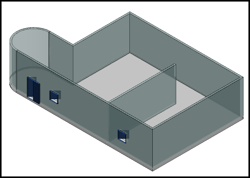
Place Doors and Windows in Walls——讲解
在墙壁上放置门窗
In the last course you learned how to place walls.
在上一门课程中,您学习了如何放置墙壁。
In this course, you will see how you can place doors, windows, and louvers in walls and slabs in a model by using the Place Equipment command and selecting the desired items from the architectural section of the equipment catalog.
在本课程中,您将了解如何使用“放置设备”命令并从设备目录的建筑部分中选择所需的项目,在模型中的墙壁和楼板上放置门、窗和百叶窗。
When placing a door, a window, or a louver, identify the point on the surface of the wall where you want the design object to be placed.
放置门、窗或百叶窗时,请在墙壁表面上确定要放置设计对象的点。
This point identifies the wall in which the opening will be cut and the position where the design object will be placed on the wall.
此点标识将在其中切割开口的墙壁以及将设计对象放置在墙壁上的位置。
Demonstration—Placing a Door in a Wall——【操作】门
演示 — 在墙上放置门
This video demonstrates placing a simple swing door in a wall. Activate the PinPoint ribbon, and then select Reposition Target.
此视频演示了如何在墙上放置简单的旋转门。激活 PinPoint 功能区,然后选择“重新定位目标”。
Set the pinpoint target at the corner of the north wall. Select Place Equipment on the vertical toolbar.
将精确定位目标设置在北墙的角落。在垂直工具栏上选择“放置设备”。
In the Select Equipment dialog, expand the Equipment, Architectural, Doors, Swing Doors Simple, and then select Swing Door Simple Left Push.
在“选择设备”对话框中,展开“设备”、“建筑”、“门”、“旋转门简单”,然后选择“旋转门简单左推”。
Select OK. The Equipment Properties dialog displays where you can define the new door's properties. Select okay.
选择“确定”。设备属性”对话框显示,您可以在其中定义新门的属性。选择“确定”。
On the Place Equipment ribbon, make sure that the positional relationship is set to Mate. Set name to Door-101.
在“放置设备”功能区上,确保位置关系设置为“配对”。将名称设置为 Door-101。
For System, select A2, U05, Structural, Miscellaneous. In Offset, key in 0 feet to position the door frame on the surface of the wall.
对于“系统”,选择“A2”、“U05”、“结构”、“杂项”。在“偏移”中,输入 0 英尺以将门框定位在墙的表面上。
In the PinPoint ribbon, key in minus 2 feet in the North field, and 0 feet in the Elevation field.
在 PinPoint 功能区中,在“北”字段中输入负 2 英尺,在“高程”字段中输入 0 英尺。
Leave the East dimension unlocked so the cursor position still locates the wall surface. Select the wall's surface when the surface is highlighted and the arrow is pointing out from it. The wall's surface must be located to automatically create the opening in the wall. Click in the graphic view to place the door in the model.
保持东向尺寸解锁,以便光标位置仍然位于墙面。当表面突出显示且箭头指向墙面时,选择墙面。必须定位墙面才能自动在墙上创建开口。单击图形视图以将门放置在模型中。
Demonstration—Placing a Window in a Wall——【操作】窗
演示 — 在墙上放置窗户
This video demonstrates placing a window in a wall. On the PinPoint ribbon, select Reposition Target and set the pinpoint target at the corner of the door.
此视频演示了如何在墙上放置窗户。在 PinPoint 功能区上,选择“重新定位目标”,并将精确定位目标设置在门的角落。
Select Place Equipment on the vertical toolbar. The Place Equipment ribbon and the Select Equipment dialog display. In the Select Equipment dialog, expand Equipment, Architectural, Windows, Residential Windows, and select Residential Windows Left Push. Select OK. The Equipment Properties dialog displays where you can define the properties for the new window. For now, select OK to return to the graphic view.
在垂直工具栏上选择“放置设备”。显示“放置设备”功能区和“选择设备”对话框。在“选择设备”对话框中,展开“设备”、“建筑”、“窗户”、“住宅窗户”,然后选择“住宅窗户左推”。选择“确定”。显示“设备属性”对话框,您可以在其中定义新窗户的属性。现在,选择“确定”返回图形视图。
On the Place Equipment ribbon, make sure that the positional relationship is set to Mate. Set Name to Window-101.
在“放置设备”功能区上,确保位置关系设置为“配对”。将“名称”设置为“窗口-101”。
Set System to A2, U05, Structural, Miscellaneous. On the PinPoint ribbon, key in -10 feet in the North box, and 4 feet in the Elevation box. Leave East unlocked so the cursor position can locate the wall surface.
将“系统”设置为“A2、U05、结构”、“杂项”。在 PinPoint 功能区上,在“北”框中输入 -10 英尺,在“高程”框中输入 4 英尺。保持“东”处于解锁状态,以便光标位置可以定位墙面。
Select when the wall surface is highlighted with an arrow is pointing out from it. Click in the graphic view to place the window in the model.
当墙面突出显示且有箭头指向墙面时,选择“选择”。单击图形视图以将窗口放置在模型中。
Summary
总结
In this course, you learned about placing architectural elements such as doors, windows, and louvers in a structure by using the Place Equipment command.
在本课程中,您学习了如何使用放置设备命令在结构中放置门、窗和百叶窗等建筑元素。
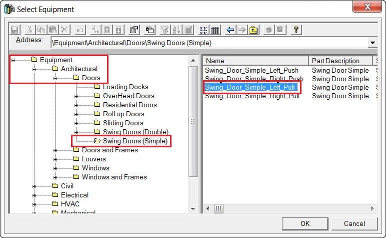
Door and window placement generates geometry of the door/window and creates an appropriately sized rough opening in the wall. When placing a door, a window, or a louver, identify the point on the surface of the wall where you want the design object to be placed. It is also effective to simply use PinPoint or Point Along to define the final position along the wall.
门窗放置会生成门/窗的几何图形,并在墙上创建一个大小合适的粗糙开口。放置门、窗或百叶窗时,确定要放置设计对象的墙面上的点。简单地使用 PinPoint 或 Point Along 定义沿墙的最终位置也是有效的。
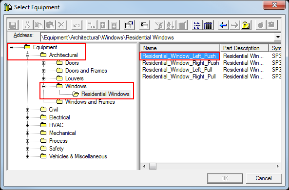
Place Openings
放置开孔
- Explain different methods for placing an opening.
- Place an opening by boundaries.
- Place an opening by sketch.
-
Place an opening by standard 2D shape.
-
解释放置开孔的不同方法。
- 按边界放置开孔。
- 按草图放置开孔。
- 按标准 2D 形状放置开孔。
Places an opening (hole) in a slab, wall, or member created in the Structure.
在结构中创建的板、墙或构件中放置开口(孔)。
You can define the shape of an opening by selecting the boundaries, sketching the opening outline, or using a predefined shape from the Catalog. In addition, you can control the depth of an opening to create a fully penetrating hole or a recessed opening.
您可以通过选择边界、绘制开口轮廓或使用目录中的预定义形状来定义开口的形状。此外,您可以控制开口的深度以创建完全穿透的孔或凹陷的开口。
There are different methods to place an opening in an existing slab, wall, or member. The next screen covers these methods in detail.
有多种方法可以在现有板、墙或构件中放置开口。下一个屏幕详细介绍了这些方法。
Openings Introduction
开口简介
This course explains the three methods that you can use to place an opening in an existing slab, wall, or member.
本课程介绍了在现有板、墙或构件中放置开口的三种方法。
You can control the depth of an opening to create a fully penetrating hole or a recessed opening.
您可以控制开口的深度以创建完全穿透的孔或凹陷的开口。
You can define the shape of an opening by selecting the opening boundaries, by sketching the opening outline, or by using a predefined shape delivered in the Catalog. When Placing an Opening by Boundaries, you select other design objects in the model to define the opening outline. You can also define offsets from the boundaries for the actual opening. When the design objects you referenced for the boundaries are moved or modified, the opening is automatically modified accordingly. For example, you can define an opening for a pipe that penetrates a grating.
您可以通过选择开口边界、绘制开口轮廓或使用目录中提供的预定义形状来定义开口的形状。当按边界放置开口时,您可以选择模型中的其他设计对象来定义开口轮廓。您还可以为实际开口定义与边界的偏移。当您为边界引用的设计对象被移动或修改时,开口也会自动进行相应的修改。例如,您可以为穿透格栅的管道定义开口。
When the pipe moves or changes diameter, the opening is also moved or changes diameter. When Placing an Opening by Sketch, you sketch the opening outline in the 2D environment. The sketch can consist of a closed set of lines, curves, arcs, fillets, and other drawing options and can reference other geometrical objects in the model. When Placing an Opening by Shape, you select the opening shape from the Catalog. The default Catalog contains many standard opening shapes that you can choose from.
当管道移动或改变直径时,开口也会移动或改变直径。当按草图放置开口时,您可以在 2D 环境中绘制开口轮廓。草图可以由一组封闭的直线、曲线、圆弧、圆角和其他绘图选项组成,并且可以引用模型中的其他几何对象。按形状放置开口时,您可以从目录中选择开口形状。默认目录包含许多标准开口形状供您选择。
The Catalog administrator can add custom shapes with the required default sizes to your Catalog. After placing an opening, you can resize or edit the shapes by using the sketch environment editing commands.
目录管理员可以将具有所需默认尺寸的自定义形状添加到您的目录中。放置开口后,您可以使用草图环境编辑命令调整形状的大小或编辑形状。
Methods for Placing an Opening
放置开口的方法
Placing an Opening by Boundary
按边界放置开口
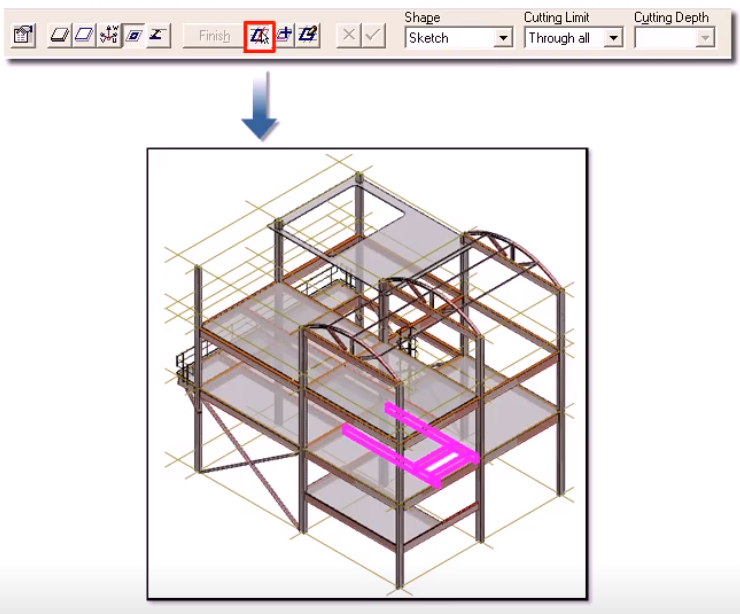
Placing an Opening by Sketch
通过草图放置开口
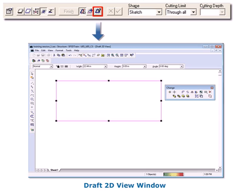
Placing an Opening by Shape
按形状放置开口
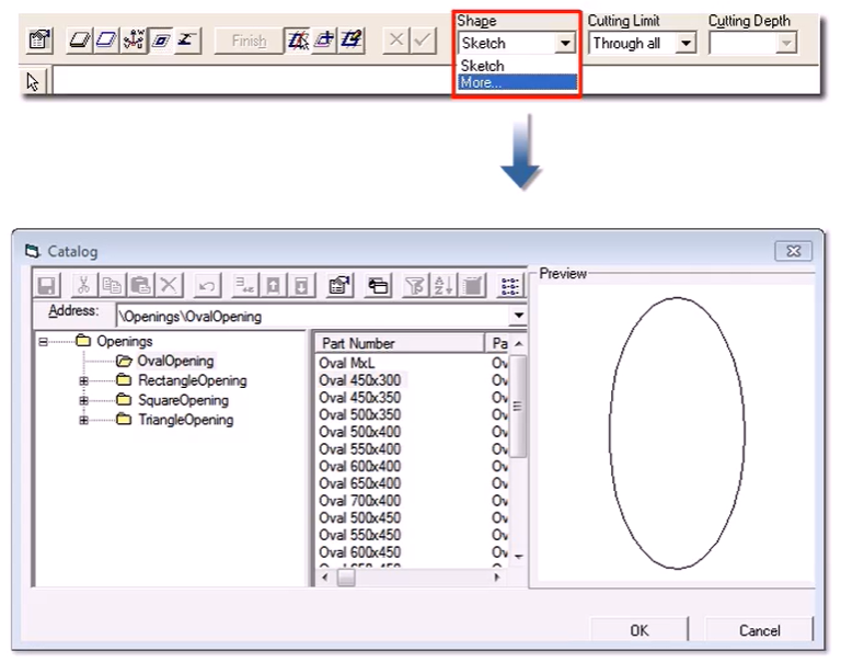
Place Opening By Boundaries——【操作】边界定义洞
按边界放置开口
This video demonstrates placing a stairway opening using the boundaries method. Select Place Opening on the vertical toolbar.
此视频演示了如何使用边界方法放置楼梯开口。在垂直工具栏上选择“放置开口”。
Select the slab located on the first floor for the stairway opening. If the selected object is a slab, the Place Opening command skips the "Sketching Plane" smartstep and defaults the sketching plane to the top surface.
选择位于一楼的楼板作为楼梯开口。如果选定的对象是楼板,则“放置开口”命令将跳过“绘制平面”智能步骤,并将绘制平面默认为顶面。
If the selected object for the opening is a member or a wall, you are prompted to select the sketching plane.
如果选定的开口对象是构件或墙,系统将提示您选择绘制平面。
The boundaries are defined on, or projected to this plane, and later projected as a cutter perpendicular to this plane toward the object in which you are placing the opening. The penetration depth is measured from the selected sketch surface.
边界在此平面上定义或投影到此平面,然后作为垂直于此平面的切割器投影到您要放置开口的对象。穿透深度是从选定的草图表面测量的。
Set Cutting Limit to Through All to specify that the opening goes all the way through the slab.
将切割限制设置为“穿过所有”,以指定开口完全穿过楼板。
Select the members that define the boundaries of the opening. You must select the boundary objects in a clockwise or counterclockwise direction.
选择定义开口边界的构件。您必须按顺时针或逆时针方向选择边界对象。
If your selected boundaries result in multiple closed shapes, the command prompts you to select the closed shapes that should be combined to form the opening. Select Finish to create the opening in the slab.
如果所选边界导致多个闭合形状,则命令会提示您选择应组合以形成开口的闭合形状。选择“完成”以在板中创建开口。
Place Opening By Catalog Shape——【操作】——2D
按目录形状放置开口
This video demonstrates placing an opening on the roof deck using a standard opening shape. select Place opening on the vertical toolbar select the roof deck located at elevation 44 feet. Select more in the shape list to select the opening shape from the catalog. Your catalog administrator can add sizes that go with your stairways or other standards
此视频演示了如何使用标准开口形状在屋顶板上放置开口。选择垂直工具栏上的“放置开口”选择位于海拔 44 英尺处的屋顶板。在形状列表中选择“更多”以从目录中选择开口形状。您的目录管理员可以添加与您的楼梯或其他标准相匹配的尺寸
You can edit the size after the opening shape is placed. Select the opening shape and size from the catalog browser.
放置开口形状后,您可以编辑尺寸。从目录浏览器中选择开口形状和尺寸。
Select ok to place the shape in sketch 2D. Edit the opening size by selecting edit properties. Define the opening with a link of 216 inches(2) with 130 inches(3) and Corners radius 12 inches(1). Rotate the opening and position it offset from the roof deck edges.
选择“确定”以将形状放置在 2D 草图中。通过选择“编辑属性”来编辑开口尺寸。使用 216 英寸的链接定义开口,其中 130 英寸,角半径为 12 英寸。旋转开口并将其放置在与屋顶板边缘偏移的位置。
select close in the sketch 2D window select finish to place the opening in the model.
在 2D 草图窗口中选择“关闭”选择“完成”以将开口放置在模型中。
Place Opening By Sketching——【操作】2D-绘制
通过绘制草图放置开口
This video demonstrates placing an opening on the roof deck using the Sketch 2D method.
此视频演示了如何使用 Sketch 2D 方法在屋顶板上放置开口。
Select Place Opening on the vertical toolbar to open the Place Opening ribbon. Select the roof deck located at Elevation 44 feet. You can optionally define the orientation that you will see in the Sketch 2D editor using the Define Orientation option. This option allows you to specify the edge that will appear at the bottom of the Sketch 2D view. Or you can select the end point that you want to display on the left side in the Sketch 2D graphic view. Select the Boundary option. If you want to sketch the opening relative to the other geometry in the 3D model, then select the "Add References to Sketch 2D" option on the ribbon. You can then select the geometry that will be projected to the sketch plane for reference as you draw the opening in the Sketch 2D editor. When you create relationships to this reference geometry, the opening is updated when the parent geometry changes. This allows you to define an opening, for example, which is positioned relative to a pipe going through the platform. When the pipe is moved, the opening will also move.
在垂直工具栏上选择“放置开口”以打开“放置开口”功能区。选择位于海拔 44 英尺处的屋顶板。您可以使用“定义方向”选项选择性地定义您将在 Sketch 2D 编辑器中看到的方向。此选项允许您指定将出现在 Sketch 2D 视图底部的边缘。或者,您可以选择要在 Sketch 2D 图形视图左侧显示的端点。选择“边界”选项。如果您想相对于 3D 模型中的其他几何图形绘制开口,请选择功能区上的“添加对 Sketch 2D 的引用”选项。然后,您可以选择在 Sketch 2D 编辑器中绘制开口时将投影到草图平面以供参考的几何图形。当您创建与此参考几何图形的关系时,开口会在父几何图形发生变化时更新。例如,这允许您定义一个开口,该开口相对于穿过平台的管道定位。当管道移动时,开口也会移动。
You can also position the opening by defining the dimensions from the edge of the slab. If the slab edges are modified, the opening will also be modified, maintaining the distance that you defined from the edge of the slab.
您还可以通过定义距板边缘的尺寸来定位开口。如果修改了板边缘,开口也会被修改,保持您定义的距板边缘的距离。
If you do not create relationships from the sketch geometry to the model geometry to control the position of the opening, then the opening will stay at the position in space where you defined it when you edit the boundaries of the slab in which the opening is defined.
如果您没有创建从草图几何图形到模型几何图形的关系来控制开口的位置,那么当您编辑定义开口的板的边界时,开口将停留在空间中您定义的位置。
Select the Draw option to open the Draft 2D View window. The Sketch 2D editor will display the boundaries of the slab and other reference objects that you selected. Draw the opening by using the drawing commands available in the 2D environment.
选择“绘制”选项以打开“草图 2D 视图”窗口。草图 2D 编辑器将显示您选择的板的边界和其他参考对象。使用 2D 环境中可用的绘图命令绘制开口。
The Sketch 2D editor has graphic indicators of the relationships and dimensions that you create. You can select these indicators and delete them to remove the relationships.
草图 2D 编辑器具有您创建的关系和尺寸的图形指示器。您可以选择这些指示器并删除它们以删除关系。
You can also choose an option to reset the relationships by using Maintain Relationships on the Dimension/Relationship toolbar.
您还可以使用“尺寸/关系”工具栏上的“维护关系”选择重置关系的选项。
Select Close on the ribbon to return to the 3D graphic view. Notice that the opening location is highlighted.
选择功能区上的“关闭”以返回 3D 图形视图。请注意,开口位置已突出显示。
Select Finish to place the opening.
选择“完成”以放置开口。
Summary
总结
You have viewed the three methods that you can use to place an opening in an existing slab, wall or member.
您已了解了在现有板、墙或构件中放置开口的三种方法。
- Placing an Opening by Boundary
- Placing an opening on the roof deck using the Sketch 2D method.
-
Placing an opening by Catalog Shape
-
按边界放置开口
- 使用草图 2D 方法在屋顶板上放置开口。
- 按目录形状放置开口
Place Stairs and Ladders
放置楼梯和梯子
Introduction——讲解
简介
This course will introduce you to placing stairs and ladders in your model. The stair and ladder design objects generate geometry sufficiently detailed for general arrangement drawings and for participation in interference detection. However, the 3D model does not contain all the details needed for stairs and ladders fabrication. The design objects do not create individual parts with fabrication identities and properties. This is similar to the function of the handrail and equipment design objects in the 3D model.
本课程将向您介绍如何在模型中放置楼梯和梯子。楼梯和梯子设计对象会生成足够详细的几何图形,用于绘制总体布置图和参与干涉检测。但是,3D 模型并不包含楼梯和梯子制造所需的所有细节。设计对象不会创建具有制造标识和属性的单个部件。这类似于 3D 模型中扶手和设备设计对象的功能。
The properties of the stairs and ladders can be used along with standards as specifications for the detailed design.
楼梯和梯子的属性可以与标准一起用作详细设计的规范。
Different types of stairs and ladders are defined in the Catalog with associated graphic symbols. The default Catalog has several types of stairs and ladders with many different options. You will need to place the different types and experiment with the options to understand all the configurations that are available to you. Your company can develop custom stairs and ladders to serve your specific requirements.
目录中定义了不同类型的楼梯和梯子以及相关的图形符号。默认目录有几种类型的楼梯和梯子,具有许多不同的选项。您需要放置不同类型的楼梯和梯子并尝试使用这些选项来了解所有可用的配置。您的公司可以开发定制的楼梯和梯子以满足您的特定要求。
All stairs and ladders, however, use the same set of graphic inputs for the positioning and construction of the geometry.
但是,所有楼梯和梯子都使用同一组图形输入来定位和构造几何图形。
The stair or ladder top is related to an object edge while the stair or ladder bottom is related to a plane.
楼梯或梯子的顶部与对象边缘相关,而楼梯或梯子的底部与平面相关。
The distance between the edge and plane defines the height. The position of the stair or ladder along the top edge is defined by an offset from a reference edge.
边缘和平面之间的距离定义了高度。楼梯或梯子沿顶部边缘的位置由与参考边缘的偏移定义。
The offset value can be either keyed in or established by graphically indicating the point. The graphically defined height combined with the properties of the construction determines the number and position of the steps or rungs. Because the stair or ladder is connected to the top edge and the bottom plane, the interference detection service will not detect interference between any part of the object, such as the stringer, handrail, and tread with the edge or bottom surface. You can define the height dimension for the stair operation envelope.
偏移值可以键入,也可以通过图形指示点来确定。图形定义的高度与构造的属性相结合,决定了台阶或横档的数量和位置。由于楼梯或梯子连接到顶部边缘和底部平面,因此干扰检测服务不会检测对象的任何部分(例如梯梁、扶手和踏板)与边缘或底部表面之间的干扰。您可以定义楼梯操作包络的高度尺寸。
This dimension is used by interference checking to check for head clearance above the stair.
干扰检查使用此尺寸来检查楼梯上方的头部间隙。
Demonstration—Placing Stairs in a Model——【操作】斜梯
演示 — 在模型中放置楼梯
This video demonstrates placing a stair in the model. Select Place Stair on the vertical toolbar to open the Select Stair dialog. Select the stair type StairA1Net, and select OK. The stair you selected becomes the default selection for the next time you place a stair. Your company can create standard sizes in your Catalog, so you just have to select the needed standard and do not have to enter sizing data. Select the top edge of the opening to define the stair's top elevation.
此视频演示了如何在模型中放置楼梯。选择垂直工具栏上的“放置楼梯”以打开“选择楼梯”对话框。选择楼梯类型 StairA1Net,然后选择“确定”。您选择的楼梯将成为下次放置楼梯时的默认选择。您的公司可以在目录中创建标准尺寸,因此您只需选择所需的标准,而不必输入尺寸数据。选择开口的顶部边缘以定义楼梯的顶部高程。
Select the slab on the level below to define the stair's bottom plane. Select the opening's side as the stair's reference edge.
选择下面楼层的楼板以定义楼梯的底部平面。选择开口的一侧作为楼梯的参考边缘。
The stairs appear in dynamics. On the ribbon, select Side to toggle on which side of the top edge the stairs are placed. Set System to Miscellaneous. Leave the stair width set to 2 feet 6 inches.
楼梯出现在动态中。在功能区上,选择“侧面”以切换楼梯放置在顶部边缘的哪一侧。将系统设置为杂项。将楼梯宽度设置为 2 英尺 6 英寸。
Set the Angle to 32 degrees. Leave the maximum pitch between treads set to 10 inches. For the Horizontal offset, key in 1 foot 9 inches. Select Finish. The stairs are created in the model database and then remain selected.
将角度设置为 32 度。将踏板之间的最大间距设置为 10 英寸。对于水平偏移,输入 1 英尺 9 英寸。选择“完成”。楼梯在模型数据库中创建,然后保持选中状态。
The stair name automatically appears in the Name box following the name rule. You can edit the name to switch to a user-defined name.
楼梯名称将按照名称规则自动显示在“名称”框中。您可以编辑名称以切换到用户定义的名称。
You can also edit any of the properties on the ribbon or on the property pages while the stair is selected.
您还可以在选择楼梯时编辑功能区或属性页面上的任何属性。
Demonstration—Placing a Ladder in a Model——【操作】直梯
演示 — 在模型中放置梯子
This video demonstrates placing a ladder in the model. Select Place Ladder on the vertical toolbar. For the ladder Type, select LadderA1 and select OK. This ladder type becomes the default the next time you place a ladder.
此视频演示了如何在模型中放置梯子。选择垂直工具栏上的“放置梯子”。对于梯子类型,选择 LadderA1 并选择“确定”。下次放置梯子时,此梯子类型将成为默认类型。
Your company can create standard sizes in your Catalog so you just have to select the needed standard without having to enter sizing data. Select the top edge to define the ladder's top elevation. Select the slab to define the ladder's bottom plane.
您的公司可以在目录中创建标准尺寸,因此您只需选择所需的标准,而无需输入尺寸数据。选择顶部边缘以定义梯子的顶部高程。选择板以定义梯子的底部平面。
Select the beam as the ladder's reference edge. On the ribbon, set the System to Miscellaneous. Leave the Width set to 2 feet and the rung pitch set to 1 foot.
选择梁作为梯子的参考边缘。在功能区上,将系统设置为杂项。将宽度设置为 2 英尺,将梯级间距设置为 1 英尺。
For the Horizontal offset, type in 5 feet. Select Finish to place the ladder. The stairs and ladders are defined with an Operation aspect and you can set the height of this aspect. The remaining volume properties are a driven by the stair or ladder dimensions.
对于水平偏移,输入 5 英尺。选择完成以放置梯子。楼梯和梯子使用操作方面定义,您可以设置此方面的高度。其余体积属性由楼梯或梯子尺寸驱动。
You can review the operational aspect associated with the stair or ladder by selecting the Format, View command and selecting the Operation aspect.
您可以通过选择“格式”、“视图”命令并选择“操作”方面来查看与楼梯或梯子相关的操作方面。
Summary
总结
In this course, you learned about placing stairs by using the Place Stair command.
在本课程中,您学习了如何使用“放置楼梯”命令放置楼梯。
Key points to remember:
要记住的要点:
As you select the top edge, bottom plane, and reference edge in the model, the appropriate primary parameter options are displayed on the Place Stair ribbon.
当您在模型中选择顶部边缘、底部平面和参考边缘时,“放置楼梯”功能区上会显示相应的主要参数选项。

The final view of stairs created in the model database will resemble the following graphic.
在模型数据库中创建的楼梯的最终视图将类似于下图。
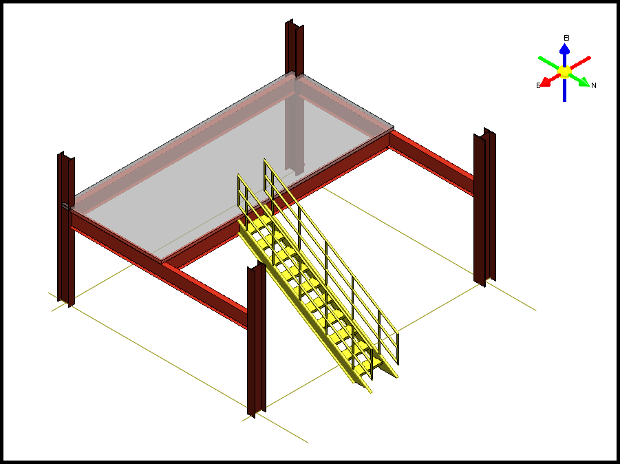
You also learned about placing ladders by using the Place Ladder command.
您还学习了如何使用“放置梯子”命令放置梯子。
- You should select the top edge of the beam to define the ladder's top elevation.
- Select the slab to define the ladder's bottom plane.
-
Select the beam as the ladder's reference edge.
-
您应该选择梁的顶部边缘来定义梯子的顶部高程。
- 选择板来定义梯子的底部平面。
- 选择梁作为梯子的参考边缘。
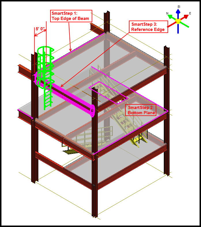
Place Handrails
放置扶手
- Place handrails in the model using the by-member method.
- Place handrails in the model using the by-path method.
-
Convert handrails to customizable individual members.
-
使用按构件方法在模型中放置扶手。
- 使用按路径方法在模型中放置扶手。
- 将扶手转换为可自定义的单个构件。
Introduction
介绍
A handrail is used in traffic areas to keep workers safe on walkways.
扶手用于交通区域,以确保工人在人行道上的安全。
You place a handrail along a 3D path by using the Place Handrail command. The handrail path can be straight, curved, or a combination of both.
您可以使用“放置扶手”命令沿 3D 路径放置扶手。扶手路径可以是直线、曲线或两者的组合。
You can place a handrail relative to one or more members by using the Place Handrail by Member command. This command defines the points of the handrail path by the end points of the selected members.
您可以使用“按构件放置扶手”命令相对于一个或多个构件放置扶手。此命令通过选定构件的端点定义扶手路径的点。
More About Handrails
有关扶手的更多信息
In this course, we will go through the procedure for placing handrails in a structure by path and by structure member.
在本课程中,我们将介绍按路径和结构构件在结构中放置扶手的过程。
We will also cover how to convert a handrail to individual member systems that allows for heavy customization.
我们还将介绍如何将扶手转换为允许大量定制的单独构件系统。
You place handrails along a 3D path by using the Place Handrail command. The handrail path can be straight, curved, or a combination of both.
您可以使用“放置扶手”命令沿 3D 路径放置扶手。扶手路径可以是直线、曲线或两者的组合。
The points of the path can be on the same plane or can be at different elevations. The points you identify for the path will create the indicated relationships to the objects when the Smart Sketch glyphs are displayed when you enter the point. When those objects move, the handrail will move.
路径的点可以位于同一平面上,也可以位于不同的高度。当您输入点时,显示智能草图符号时,您为路径标识的点将与对象创建指示的关系。当这些对象移动时,扶手也会移动。
You can place a handrail relative to one or more members by using the Place Handrail by Member command.
您可以使用“按构件放置扶手”命令相对于一个或多个构件放置扶手。
This command defines the points of the handrail path by the end points of the selected members. It creates a separate handrail for every member.
此命令通过所选构件的端点定义扶手路径的点。它为每个构件创建一个单独的扶手。
If the members are end-connected, the handrails will also appear end-connected. The end result is a handrail that could have been created by the Place Handrail command and selecting the ends of the member as the path points. The Convert command on the Place Handrail ribbon enables you to break up existing handrails into separate member parts. This is helpful when you want to customize a handrail to suit some aspect of your project.
如果构件是端连接的,扶手也会显示为端连接的。最终结果是扶手,它可以通过“放置扶手”命令并选择构件的末端作为路径点来创建。“放置扶手”功能区上的“转换”命令使您可以将现有扶手分解为单独的构件部分。当您想要自定义扶手以适应项目的某些方面时,这很有用。
Handrail types are defined in the catalog with associated graphic symbols. The default catalog has several handrails with different options.
扶手类型在目录中定义,并带有相关的图形符号。默认目录有几个带有不同选项的扶手。
You will need to place a handrail and experiment with the options to understand all the configurations available to you.
您需要放置扶手并尝试使用选项来了解所有可用的配置。
The handrail design object generates geometry sufficiently detailed for general arrangement drawings and for participation in interference detection.
扶手设计对象会生成足够详细的几何图形,用于总体布置图和参与干涉检测。
Like ladders or stairways, the software does not, by default, create separate parts with fabrication identities and properties.
与梯子或楼梯一样,默认情况下,软件不会创建具有制造标识和属性的单独部件。
The handrail is defined with an operation aspect for interference checking. You cannot change the size of this aspect, only your catalog administrator can create custom handrails that contain the properties to resize its operation aspect. To view the operation aspect, click the Format, View command and select the operation aspect.
扶手定义了一个用于干涉检查的操作方面。您无法更改此方面的大小,只有您的目录管理员可以创建包含属性的自定义扶手以调整其操作方面的大小。要查看操作方面,请单击“格式”、“查看”命令并选择操作方面。
Demonstration—Place Handrail by Member——【操作】按构件放置扶手
演示 — 按构件放置扶手
This video demonstrates placing handrails by member in the model. Click Place Handrail by Member on the vertical toolbar.
此视频演示了如何在模型中按构件放置扶手。单击垂直工具栏上的按构件放置扶手。
The default Catalog contains many handrails. Browse to the Handrail Type A Mounted to Member folder and select the Side Mounted to Member handrail type.
默认目录包含许多扶手。浏览到扶手类型 A 安装到构件文件夹并选择侧面安装到构件扶手类型。
The selected handrail will be the default selection the next time you place a handrail in the session.
下次在会话中放置扶手时,所选扶手将成为默认选择。
On the Place Handrail ribbon, set System to Miscellaneous. Set Column Clearance to 3 inches. Select the members that should have the handrails.
在放置扶手功能区上,将系统设置为杂项。将柱间隙设置为 3 英寸。选择应该有扶手的构件。
Select Accept. The command automatically moves to the Select walking surface smartstep. You need to select the walking surface location in the graphic view so that the software can identify which member side to place the handrail on (opposite of the walking side), and to calculate the toe-plate and railing height. Select the end treatments as needed, and then select Finish to place the handrails.
选择接受。命令自动移动到选择行走表面智能步骤。您需要在图形视图中选择行走表面位置,以便软件可以识别在构件的哪一侧放置扶手(与行走侧相反),并计算脚板和栏杆高度。根据需要选择端部处理,然后选择完成以放置扶手。
Place Handrails by Path——【操作】按路径放置扶手
按路径放置扶手
Places a handrail along a path that you specify in the model. The handrail path can be straight, curved, or a combination of both and can be on the same plane or transverse multiple elevations.
沿着您在模型中指定的路径放置扶手。扶手路径可以是直线、曲线或两者的组合,并且可以位于同一平面上或横跨多个立面。
Because handrails are placed along a defined path, moving other objects in the model might not affect the position of the handrail. The points you identify for the path will create the indicated relationships to the objects when the SmartSketch glyphs are displayed as you enter the point. When those objects move, the handrail will be modified.
由于扶手是沿着定义的路径放置的,因此移动模型中的其他对象可能不会影响扶手的位置。当您输入点时显示 SmartSketch 字形时,您为路径标识的点将与对象创建指示的关系。当这些对象移动时,扶手将被修改。
This video demonstrates placing handrails by path in the model. Select Place Handrail on the vertical toolbar. Browse to the Handrail Type A Mounted to Member folder and select the Side Mounted to Member handrail type. Sketch the path that the handrail is to follow.
此视频演示了如何按路径在模型中放置扶手。在垂直工具栏上选择“放置扶手”。浏览到扶手类型 A 安装到构件文件夹,然后选择侧面安装到构件扶手类型。绘制扶手要遵循的路径。
Select Finish when you are done defining the path. On the Place Handrail ribbon, select Toggle Side to define on which side of the path to place the handrail. Select the end treatments as needed, and then select Finish to place the handrail.
定义完路径后,选择“完成”。在“放置扶手”功能区上,选择“切换侧面”以定义在路径的哪一侧放置扶手。根据需要选择末端处理,然后选择“完成”以放置扶手。
Handrails Conversion Process
扶手转换过程
Handrails in Smart 3D are symbol-based objects, which do not allow user modification. They can however be converted into customizable models when heavy modification of the handrail is required.
Smart 3D 中的扶手是基于符号的对象,不允许用户修改。但是,当需要对扶手进行大量修改时,可以将它们转换为可自定义的模型。
You should convert a handrail when you want to edit the positions of individual posts, rails, or perform some other handrail customization that cannot be done using the handrail symbol properties. Handrails that you have converted to member parts cannot be converted back to a handrail symbol. To delete a converted handrail, you will need to delete each handrail part individually.
当您想要编辑单个柱子、扶手的位置或执行无法使用扶手符号属性完成的其他扶手自定义时,您应该转换扶手。已转换为构件部分的扶手无法转换回扶手符号。要删除转换后的扶手,您需要单独删除每个扶手部分。
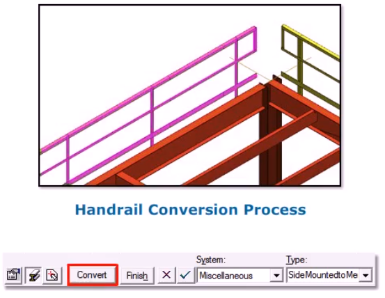
【操作】拆分扶手
As you have learned, handrails are, by default, symbol-based objects which do not allow user modification. Handrails can, however be converted into customizable model objects when heavy modification of the handrail is required.
正如您所了解的,默认情况下,扶手是基于符号的对象,不允许用户修改。但是,当需要对扶手进行大量修改时,可以将扶手转换为可自定义的模型对象。
For this demonstration, we'll show creating a gap in a handrail to provide clear access for a ladder. Select the handrail to convert. Select Convert on the ribbon to break down the handrail into the individual objects, making the handrail a system parent of the new objects. Note the warning dialog reminding you that handrails that you convert to member parts cannot be converted back to a single handrail symbol. Select Yes.
为了演示,我们将展示如何在扶手上创建一个间隙,以便为梯子提供畅通的通道。选择要转换的扶手。选择功能区上的“转换”将扶手分解为单个对象,使扶手成为新对象的系统父对象。请注意警告对话框,提醒您转换为构件部分的扶手无法转换回单个扶手符号。选择“是”。
Now, look at your workspace explorer. Notice how the handrail has become a system parent with individual members parts。
现在,查看您的工作区资源管理器。注意到扶手如何成为具有单个构件部分的系统父级。
We can now choose a part of the handrail to modify here, or in a graphic view. Move the handrail post to the side.
我们现在可以选择扶手的一部分在这里或在图形视图中进行修改。将扶手柱移到一侧。
Then copy paste the post to the other side of the ladder
然后将柱复制粘贴到梯子的另一侧
Now, we will split the entire handrail vertically using the Place Split command to create a gap for ladder access.
现在,我们将使用“放置拆分”命令垂直拆分整个扶手,以创建梯子通道的间隙。
Select Place Split on the vertical toolbar. Select By Point on the ribbon. Select the top rail member on the converted handrail.
在垂直工具栏上选择“放置拆分”。在功能区上选择“按点”。选择转换后的扶手上的顶部栏杆构件。
Split the member on one side of the ladder.
在梯子的一侧拆分构件。
We need to place a second split that will allow us to create a gap. So repeat the process on the other side of the ladder.
我们需要放置第二个拆分,以便创建间隙。因此,请在梯子的另一侧重复该过程。
The top rail member should now be split into three member parts. Select the middle part of the top rail and select Convert to Member System on the member part ribbon bar. This will now convert the member parts to independent member systems, which can be selected and deleted. This will create a gap on the top rail of the handrail.
现在应将顶部栏杆构件拆分为三个构件部分。选择顶部栏杆的中间部分,然后在构件部分功能区栏上选择“转换为构件系统”。这会将构件部分转换为独立的构件系统,可以选择和删除这些构件系统。这将在扶手的顶部栏杆上创建间隙。
Now, follow the above procedure to split the other rail members and create a gap on the entire handrail.
现在,按照上述步骤拆分其他栏杆构件并在整个扶手上创建间隙。
Summary
总结
In this course, you learned about placing a handrail in a model using the by-path and by-member methods as well as converting them to individual parts so they may be modified to suit your design purposes.
在本课程中,您学习了如何使用按路径和按成员方法在模型中放置扶手,以及如何将其转换为单独的部件,以便对其进行修改以满足您的设计目的。
Place Footings
放置地基
Work with Footings
使用基础
There are two types of footings that you can place:
您可以放置两种类型的基础:
Single Footing: A single footing supports a single column.
单基础:单基础支撑单柱。
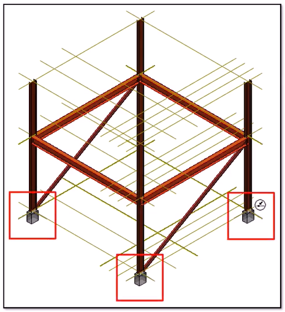
Combined Footing: A combined footing supports multiple columns and requires a minimum of two columns for placement. When placing a combined footing with a merged pier, all columns must have the same bottom elevation.
组合基础:组合基础支撑多个柱子,至少需要两个柱子才能放置。放置带有合并墩的组合基础时,所有柱子的底部高程必须相同。
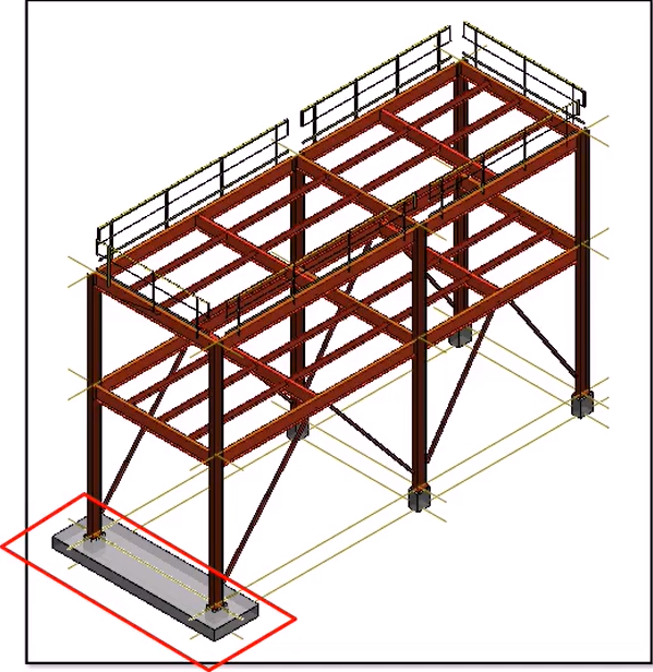
There are two methods for placing footings:
放置基础有两种方法:
By Member: You select the bottoms of columns to position the footing.
按构件:选择柱子的底部来放置基础。
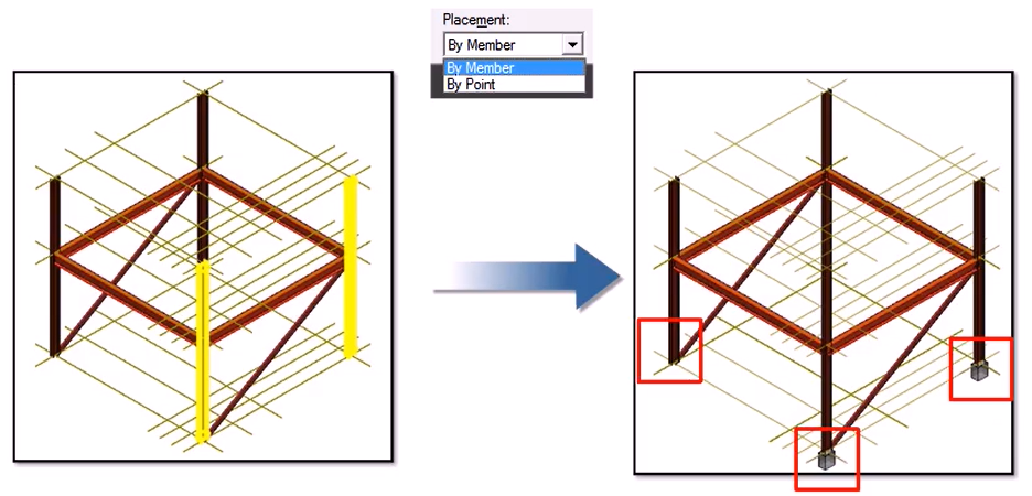
By Point: You place the footing at a specific point. This method is normally used to place footings relative to grid intersections before placing members.
按点:将基础放置在特定点。此方法通常用于在放置构件之前相对于网格交叉点放置基础。
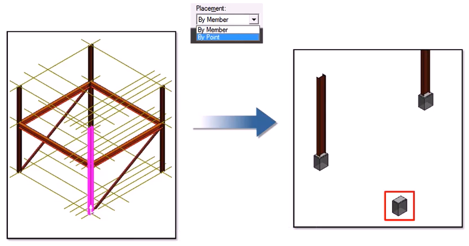
More About Footings
有关基础的更多信息
This course explains how to place single and combined footings. The footing generates geometry with a single identity that is sufficiently detailed for general arrangement drawings and for participation in interference detection. It does not create multiple separate parts with fabrication identities and properties.
本课程介绍如何放置单个和组合基础。基础生成具有单一标识的几何图形,该标识足够详细,可用于总体布置图和参与干涉检测。它不会创建具有制造标识和属性的多个单独部件。
A typical footing is comprised of: A base that supports one or more piers. Some footings for light-weight structures such as a light pole do not have a base. A pier that rests on the base and supports the grout layer. Some footings do not have a pier in which case the grout is put directly on the base.
典型的基础包括:支撑一个或多个桥墩的底座。一些轻型结构(例如灯杆)的基础没有底座。桥墩,位于底座上并支撑灌浆层。有些基础没有桥墩,在这种情况下,灌浆直接放在底座上。
A grout layer rests on the pier and supports the base plate. A base plate rests on the grout layer and is welded to the supported column.
灌浆层位于桥墩上并支撑底板。底板位于灌浆层上并焊接到支撑柱上。
The default structure Catalog provides several footing types. The footings in the default Catalog have properties to size the geometry for all of the above components except the anchor bolts and reinforcing bars. No properties for these components of the footing are provided.
默认结构目录提供了几种基础类型。默认目录中的基础具有属性,用于调整除锚栓和钢筋之外的所有上述组件的几何图形的大小。没有提供基础的这些组件的属性。
The Catalog administrator can add properties to the footing in the Catalog to allow you to document these components if it is important to your workflow. There are two types of footings that you can place: A single footing supports a single column.
如果这对您的工作流程很重要,目录管理员可以在目录中为基础添加属性,以便您记录这些组件。您可以放置两种类型的基础:单个基础支撑单个柱。
A combined footing supports multiple columns. A combined footing requires a minimum of two columns for placement. A combined footing with a single column is put on the To Do List.
组合基础支撑多个柱。组合基础至少需要两个柱才能放置。单个柱的组合基础放在待办事项列表中。
When placing a combined footing with a merged pier, all columns must have the same bottom elevation. The software does not allow adding a column with a different bottom elevation to the merged pier. There are two methods to place footings: By Member, where you select the ends of members to position the footing. By Point, where you place the footing at a specific point. With either placement method, footing height can be defined by the identification of the supporting surface or by entering the height of the footing, depending on the specific type of footing chosen from the Catalog.
放置带有合并墩的组合基础时,所有柱的底部高度必须相同。软件不允许将具有不同底部高度的柱添加到合并墩。放置基础有两种方法:按构件,您可以选择构件的末端来定位基础。按点,您可以将基础放置在特定点。无论使用哪种放置方法,都可以通过识别支撑表面或输入基础的高度来定义基础高度,具体取决于从目录中选择的特定基础类型。
Demonstration—Place Single Footings by Member——【操作】Member,单个
演示 — 按构件放置单个基础
This video demonstrates placing single rectangular footings under columns by using the Place Footing command. Select Place Footing on the vertical toolbar.
此视频演示了如何使用“放置基础”命令在柱下放置单个矩形基础。在垂直工具栏上选择“放置基础”。
On the ribbon, set the Placement type to By Member to place footings at the bottom of members that you specify.
在功能区上,将放置类型设置为“按构件”,以将基础放置在您指定的构件底部。
In the Type list, select More. In the Select Footing dialog, expand the Assemblies hierarchy, Assemblies > Single > Pier FootingAsm folder, select RectPierFootingAsm to place single rectangular footings, and then select OK. For the System, select A2, U02, Structural, Footings.
在“类型”列表中,选择“更多”。在“选择基础”对话框中,展开“组件”层次结构、“组件”>“单个”>“Pier FootingAsm”文件夹,选择“RectPierFootingAsm”以放置单个矩形基础,然后选择“确定”。对于“系统”,选择“A2”、“U02”、“结构”、“基础”。
Select all the columns, and then select Accept.
选择所有柱,然后选择“接受”。
Select the supporting plane if the footing type requires it, and then select Accept. The software disables the supporting plane option if the footing type does not require it.
如果基础类型需要支撑平面,请选择支撑平面,然后选择“接受”。如果基础类型不需要支撑平面,软件将禁用支撑平面选项。
Select Finish to place the footings.
选择“完成”以放置基础。
Demonstration—Place Single Footings by Point——【操作】—点
演示 — 按点放置单个基础
This video demonstrates how to place single rectangular footings by point using the Place Footing command. Select Place Footing on the vertical toolbar.
此视频演示如何使用“放置基础”命令按点放置单个矩形基础。在垂直工具栏上选择“放置基础”。
On the ribbon, select the By Point option from the Placement list to place the footing at a specified point.
在功能区上,从“放置”列表中选择“按点”选项,将基础放置在指定点。
In the Type list, click More. In the Select Footing dialog, browse to Rect Pier and Slab Footing Asm to place rectangular footings, and then select OK. For the System, select More and then select A2, U02, Structural, Footings. Identify the points where you want to place the footings and then click Accept.
在“类型”列表中,单击“更多”。在“选择基础”对话框中,浏览到“矩形墩和板基础 Asm”以放置矩形基础,然后选择“确定”。对于“系统”,选择“更多”,然后选择“A2、U02、结构、基础”。确定要放置基础的点,然后单击“接受”。
Select supporting plane. The software will automatically activate the Select Plane smartstep if it is required by the footing type you have selected.
选择支撑平面。如果您选择的基础类型需要“选择平面”智能步骤,软件将自动激活该智能步骤。
The software disables this option if the footing type you selected does not require a supporting surface. Click Finish to place the footings.
如果您选择的基础类型不需要支撑面,软件将禁用此选项。单击“完成”以放置基础。
Helpful Things to Know About Combined Footings
关于组合基础的有用信息
Combined footings require a minimum of two columns for placement. If you remove columns from a combined footing such that a single column remains, the software changes the combined footing to a single-type footing supporting the remaining column.
组合基础至少需要两根柱子才能放置。如果您从组合基础中移除柱子,只剩下一根柱子,软件会将组合基础更改为支撑剩余柱子的单一类型基础。
When placing a combined footing with a merged pier, all columns must have the same bottom elevation. Smart 3D does not allow a column with a different bottom elevation to be added to the merged pier.
放置带有合并墩的组合基础时,所有柱子的底部标高必须相同。Smart 3D 不允许将底部标高不同的柱子添加到合并墩子中。
Smart 3D places key points and control points that can be selected as layout points in drawings on combined footings. Key points are placed at the vertices of slabs and piers. Control points are placed at column locations.
Smart 3D 会将关键点和控制点放置在组合基础的图纸上,这些点和控制点可在图纸中选为布局点。关键点放置在板和墩子的顶点。控制点放置在柱子的位置。
Demonstration—Place Combined Footings by Member——【操作】——组合基础,Member
演示 — 按构件放置组合基础
This video demonstrates placing combined rectangular footings by using the Place Footing command. Select Place Footing on the vertical toolbar.
此视频演示了如何使用“放置基础”命令放置组合矩形基础。在垂直工具栏上选择“放置基础”。
On the ribbon, set the Placement type to By Member to place footings at the bottom of members that you specify.
在功能区上,将放置类型设置为“按构件”,以将基础放置在您指定的构件底部。
In the Type list, select More. In the Select Footing dialog, expand the Assemblies hierarchy, Assemblies, Pier And Slab Combined Footing Assemblies folder, select Rect Pier And Slab Comb Footing Assembly and then select OK. For the System, select A2, U02, Structural, Footings. Select the columns that you want to share a footing, and then select Accept. You must select at least two columns to place a combined footing. Select the supporting plane if the footing type requires it, and then select Accept. The software disables the supporting plane option if the footing type does not require it.
在“类型”列表中,选择“更多”。在“选择基础”对话框中,展开“组件层次结构”、“组件”、“墩和板组合基础组件”文件夹,选择“矩形墩和板组合基础组件”,然后选择“确定”。对于“系统”,选择“A2”、“U02”、“结构”、“基础”。选择要共享基础的柱,然后选择“接受”。必须至少选择两根柱才能放置组合基础。如果基础类型需要,请选择支撑平面,然后选择“接受”。如果基础类型不需要,软件将禁用支撑平面选项。
Click Finish to place the footing.
单击“完成”以放置基础。
Demonstration—Place Combined Footings by Point——【操作】——组合基础,点
演示 — 按点放置组合基础
This video demonstrates placing a combined rectangular footing using the By Point method using the Place Footing command.
此视频演示了如何使用“放置基础”命令通过“按点”方法放置组合矩形基础。
Select Place Footing on the vertical toolbar. Set the System to A2, U02, Structural, Footings. In the Type list, select More.
在垂直工具栏上选择“放置基础”。将“系统”设置为“A2、U02、结构、基础”。在“类型”列表中,选择“更多”。
In the Select Footing dialog, browse to Assemblies, Slab Combined Footing Assembly, Rectangular Slab Combined Footing Assembly, and then select OK. Identify the points where you want to place the footing. You must select at least two points to place a combined footing by points.
在“选择基础”对话框中,浏览到“组件”、“板组合基础组件”、“矩形板组合基础组件”,然后选择“确定”。确定要放置基础的点。必须至少选择两个点才能按点放置组合基础。
Select Accept when you are done selecting points. Select the supporting plane if the footing type you have selected requires it, and then select Accept. The software disables this option if the footing type you have selected does not require a supporting surface to be defined.
选择完点后,选择“接受”。如果所选的基础类型需要支撑平面,请选择支撑平面,然后选择“接受”。如果所选的基础类型不需要定义支撑面,软件将禁用此选项。
Select Finish to place the footing.
选择“完成”以放置基础。
Demonstration—Place Piles——【操作】
演示 — 放置桩
Like footings, the software can generate another type of structural support called piles.
与基础一样,该软件可以生成另一种称为桩的结构支撑。
Like footings, the software can generate another type of structural support called piles. A pile is a heavy member or post driven vertically into the bed of a soft ground surface or water way to support the foundations of a structure.
与基础一样,该软件可以生成另一种称为桩的结构支撑。桩是一种重型构件或柱子,垂直打入软地面或水道的床中,以支撑结构的基础。
You can place piles in any quantity configuration as well as set edge clearances and depth dimensions.
您可以以任意数量配置放置桩,也可以设置边缘间隙和深度尺寸。
You can also specify the member cross section and material the piles are made of. In this example, we will place 6 piles underneath the slab. Select Tools, Custom Commands to open the Custom Commands dialog, which allows you to add new custom commands. Select Add. On the Add Custom Command dialog, we need to provide the Command Program ID.
您还可以指定桩的构件横截面和材质。在此示例中,我们将在板下放置 6 个桩。选择“工具”、“自定义命令”以打开“自定义命令”对话框,该对话框允许您添加新的自定义命令。选择“添加”。在“添加自定义命令”对话框中,我们需要提供命令程序 ID。
Type in exactly as shown PileFoundation,PileFoundation.PileFoundation Name the command Place Piles. If you want, provide a short description.
输入与所示完全相同的内容 PileFoundation,PileFoundation.PileFoundation 将命令命名为 Place Piles。如果需要,请提供简短的描述。
Select okay when finished. Select the Place Piles custom command, and select Run to open the Place Piles command.
完成后选择“确定”。选择“放置桩”自定义命令,然后选择“运行”以打开“放置桩”命令。
Notice that the configuration areas are grayed out. This is because we have not chosen the surface. In this example, the piles need to be placed on the slab's bottom surface. Select anywhere on the slab's bottom surface.
请注意,配置区域呈灰色。这是因为我们没有选择表面。在此示例中,桩需要放置在板的底面上。选择板底面上的任意位置。
After the surface has been selected, select More from the System list and select a system for the piles.
选择表面后,从“系统”列表中选择“更多”,然后选择桩的系统。
There are two modes of placement, clearance and spacing. In the example, we will be using the clearance mode to place six steel-carbon piles to support our slab. Based on its shape dimensions, we need to place three piles along two equal rows with a minimum of two feet edge clearance. Our total depth should be ten feet plus six inches for the embedment depth of each pile into the slab. Enter 3 for Piles Along Length. Enter 2 for Piles Along Width.
有两种放置模式:间隙和间距。在此示例中,我们将使用间隙模式放置六个钢碳桩来支撑我们的板。根据其形状尺寸,我们需要沿两排相等的桩放置三个桩,边缘间隙至少为 2 英尺。我们的总深度应为 10 英尺加 6 英寸,这是每个桩嵌入板的深度。输入 3 作为“沿长度的桩”。输入 2 作为“沿宽度的桩”。
Set Minimum Edge Clearance to 2 feet. Set Pile Depth to 10 feet, Cross-Section to CS14, and Embedment Depth to 6 inches.
将“最小边缘间隙”设置为 2 英尺。将桩深度设置为 10 英尺,横截面积设置为 CS14,嵌入深度设置为 6 英寸。
After you have these attributes set, select okay to place the piles.
设置完这些属性后,选择确定即可放置桩。
Summary
总结
In this course, you learned to:
在本课程中,您学习了:
Place single and combined footings by member and by point using the Place Footings command.
使用“放置基础”命令按构件和点放置单个和组合基础。
Place piles in any quantity configuration. Through the Place Piles command, you can specify the number of piles in each direction as well as edge clearances and depth dimensions. You can also specify the member cross section and material for the piles.
以任意数量配置放置桩。通过“放置桩”命令,您可以指定每个方向的桩数以及边缘间隙和深度尺寸。您还可以指定桩的构件横截面和材料。
---Day3---
---Day4---
Equipment Foundations
设备基础
Introduction
简介
An equipment foundation makes the installation of equipment easier. The foundation is typically connected to the floor, deck, or wall, and the equipment is then bolted to the foundation. You can place the equipment foundation either before or after you place the equipment in the model.
设备基础使设备的安装更加容易。基础通常连接到地板、甲板或墙壁,然后将设备用螺栓固定在基础上。您可以在将设备放入模型之前或之后放置设备基础。
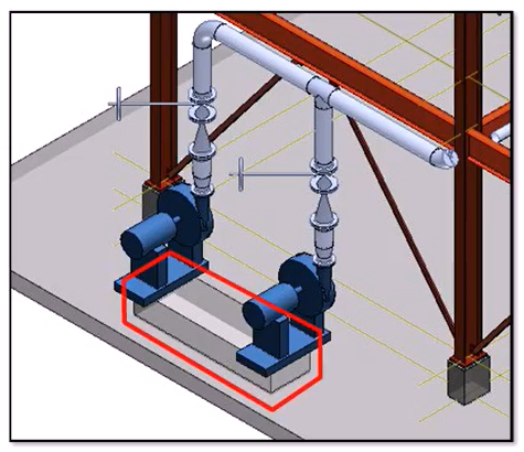
In this course, we will look at how to place equipment foundations in your model. You place equipment foundations using the Place Equipment Foundation command.
在本课程中,我们将了解如何在模型中放置设备基础。使用“放置设备基础”命令放置设备基础。
The equipment foundation types in the catalog can either generate just the geometry for the foundation as a whole, which is similar to the concept of stairs, ladders, and handrails, or create and position other design objects automatically, such as structural members with their own identity and design information. The equipment foundation design object controls the properties that you can edit on the design objects it creates, such as members. An equipment foundation is comprised of the equipment pad and the legs and supports of the foundation. All equipment foundations are placed in the same way. When equipment has a single foundation port, you identify the equipment and the mounting surface for the foundation, such as a floor or a wall.
目录中的设备基础类型可以只生成整个基础的几何图形,这类似于楼梯、梯子和扶手的概念,也可以自动创建和定位其他设计对象,例如具有自身标识和设计信息的结构构件。设备基础设计对象控制您可以在其创建的设计对象(例如构件)上编辑的属性。设备基础由设备垫块以及基础的支腿和支撑组成。所有设备基础的放置方式相同。当设备具有单个基础端口时,您可以识别设备和基础的安装表面,例如地板或墙壁。
However, if the equipment has more than one foundation port, then you identify the foundation port directly and the mounting surface for the foundation.
但是,如果设备有多个基础端口,则您可以直接识别基础端口和基础的安装表面。
The equipment's foundation port provides mounting bolt hole pattern and position information. The equipment foundation type uses this information to size the foundation.
设备的基础端口提供安装螺栓孔图案和位置信息。设备基础类型使用此信息来确定基础的大小。
You can also place equipment foundations at any point in your plant, without the need for the equipment to be placed first.
您还可以在工厂的任何位置放置设备基础,而无需先放置设备。
This is helpful when you want to place the foundation for a piece of equipment at a specific position.
当您想在特定位置放置设备基础时,这很有用。
Place an Equipment Foundation——【操作】,设备
放置设备基础
This video demonstrates placing an equipment foundation for two pumps by using the Place Equipment Foundation command. Select Place Equipment Foundation on the vertical toolbar.
On the ribbon, select the By Rule check box to allow the software to select the equipment foundation to use based on the equipment that you select. Select the two pumps. In the Type box, the software automatically selects the default foundation defined in the catalog reference data. Select Accept. Clear the By Rule check box, and then select More in the list to select the equipment foundation type yourself. In the Select equipment foundation dialog, navigate to the Assemblies folder, and select the needed equipment foundation, and then select OK. The next step is to specify the equipment foundation's supporting plane.
此视频演示了如何使用“放置设备基础”命令为两个泵放置设备基础。在垂直工具栏上选择“放置设备基础”。
在功能区上,选中“按规则”复选框,以允许软件根据您选择的设备选择要使用的设备基础。选择两个泵。在“类型”框中,软件会自动选择目录参考数据中定义的默认基础。选择“接受”。清除“按规则”复选框,然后在列表中选择“更多”,以自行选择设备基础类型。在“选择设备基础”对话框中,导航到“组件”文件夹,选择所需的设备基础,然后选择“确定”。下一步是指定设备基础的支撑平面。
Some equipment foundations do not require you to specify the supporting plane. The foundation automatically finds the surface Some equipment foundations do not require you to specify the supporting plane. The foundation automatically finds the surface that is closest under the equipment foundation. Other equipment foundations do not locate a supporting surface at all, but require you to enter the height manually. The command will prompt you for the surface if the selected foundation type requires it and you'll notice that the surface selection smartstep is active. Select the grade slab as the supporting plane.
有些设备基础不需要您指定支撑平面。基础会自动找到表面有些设备基础不需要您指定支撑平面。基础会自动找到设备基础下方最近的表面。其他设备基础根本不定位支撑表面,但需要您手动输入高度。如果所选基础类型需要表面,该命令将提示您输入表面,您会注意到表面选择智能步骤处于活动状态。选择等级板作为支撑平面。
On the ribbon, click More in the System list and select the Miscellaneous system.
在功能区上,单击系统列表中的更多,然后选择杂项系统。
Select Finish to place the equipment foundation.
选择完成以放置设备基础。
You can edit the properties of the equipment foundation. You can see a picture of the foundation that shows the meaning of the dimensions by selecting Preview.
您可以编辑设备基础的属性。通过选择预览,您可以看到基础的图片,其中显示了尺寸的含义。
Place an Equipment Foundation by Point——【操作】,点
按点放置设备基础
This video demonstrates placing an equipment foundation at any point in your plant, without the need to provide a piece of equipment as an input.
此视频演示了如何在工厂的任何位置放置设备基础,而无需提供设备作为输入。
Select Place Equipment Foundation on the vertical toolbar. On the ribbon, the Placement control defines whether the foundation is place by equipment as the primary input or By Point. Select the By Point option. Now you can use pinpoint to precisely locate where you would like to place the equipment foundation. Open the pinpoint ribbon. Make sure your active coordinate system is set to Global, and then select Set Target to Origin. You need to choose the foundation type on the Type list.
在垂直工具栏上选择“放置设备基础”。在功能区上,“放置”控件定义基础是按设备放置还是按点放置。选择“按点”选项。现在,您可以使用精确定位来精确定位您想要放置设备基础的位置。打开精确定位功能区。确保您的活动坐标系设置为“全局”,然后选择“将目标设置为原点”。您需要在“类型”列表中选择基础类型。
Select more, then expand Assemblies, Leg Angle Frame Foundation Leg Angle Equipment Foundation with Optional Plane. In the pinpoint ribbon, set East to 75 feet, North to 15 feet, and Elevation to 1 foot 6 inches. Click anywhere in the graphic view to accept the placement location of the equipment foundation. Select a parent system for the equipment foundation. Select Finish to place the equipment foundation in the model.
选择更多,然后展开“组件”、“支腿角”“框架基础”“支腿角”“设备基础(带可选平面)”。在精确定位功能区中,将“东”设置为 75 英尺,将“北”设置为 15 英尺,将“高程”设置为 1 英尺 6 英寸。单击图形视图中的任意位置以接受设备基础的放置位置。为设备基础选择一个父系统。选择“完成”以将设备基础放置在模型中。
Summary
总结
In this course, you learned about placing equipment foundations using the equipment and by point method.
在本课程中,您将学习使用设备和点法放置设备基础。
Structural Data Exchange Network Explained in Detail
结构数据交换网络详解
Overview
概述
Structural objects are imported and exported from Smart 3D using the CIMsteel Integration Standards 2.0 (CIS/2) format.
使用 CIMsteel 集成标准 2.0 (CIS/2) 格式从 Smart 3D 导入和导出结构对象。
You only export concrete objects such as slabs, walls, openings on slabs and walls, footings, equipment foundations, members, trenches, and designed equipment to the Industry Foundation Class (IFC) format. The designed equipment must have an equipment classification of civil or structural to be exported.
您只能将混凝土对象(例如板、墙、板和墙上的开口、地基、设备基础、构件、沟槽和设计设备)导出为 工业基础类 (IFC) 格式。要导出的设计设备必须具有土木或结构设备分类。
More About Structural Data Exchange
有关结构数据交换的更多信息
The global engineering and design industry has numerous facets. Contributors function in the form of partnerships working together to achieve singular engineering goals.
全球工程和设计行业有许多方面。贡献者以合作伙伴关系的形式共同努力实现单一的工程目标。
How such organizations are best facilitated comes from the sharing of information. In our age of computer-aided technologies, modern engineering and design firms collaborate across the spectrum by using standardized file formats and technical practices.
如何最好地促进此类组织来自信息共享。在我们这个计算机辅助技术时代,现代工程和设计公司通过使用标准化文件格式和技术实践在各个领域进行协作。
This is the nature of structural data exchange. The software facilitates structural data exchange using the CIMsteel Integration Standards 2.0, or CIS/2 for export and import of physical structural models. The software also provides limited support for the Industry Foundation Class, or IFC, format by exporting only concrete slabs, walls, structural systems, openings on slabs and walls, footings, equipment foundations, and design solids. This course covers how to import such data for use in your model, and how to export it out for use by others in your own data exchange network. CIS/2, or CIMSteel Integration Standards 2.0, was developed by collaborators from the Steel Construction Institute and the School of Civil Engineering at Leeds University.
这是结构数据交换的本质。该软件使用 CIMsteel 集成标准 2.0 或 CIS/2 促进结构数据交换,以导出和导入物理结构模型。该软件还通过仅导出混凝土板、墙、结构系统、板和墙上的开口、基础、设备基础和设计实体,为行业基础类 (IFC) 格式提供有限的支持。本课程介绍如何导入此类数据以供您的模型使用,以及如何将其导出以供您自己的数据交换网络中的其他人使用。 CIS/2 或 CIMSteel 集成标准 2.0 是由钢结构研究所和利兹大学土木工程学院的合作者开发的。
CIS/2 was designed to facilitate a more integrated method of working through the network of sharing between the companies involved in planning, design, analysis and construction of steel-framed or similar structures. The software provides limited support for importing and exporting the design model, importing of manufacturing models, and partial importing and exporting the analytical model, which is available only when in the Structural Analysis task.
CIS/2 旨在通过参与规划、设计、分析和建造钢框架或类似结构的公司之间的共享网络,促进一种更加集成的工作方法。该软件对导入和导出设计模型、导入制造模型以及部分导入和导出分析模型提供有限的支持,这仅在结构分析任务中可用。
IFC stands for Industry Foundation Class, which refers to a neutral format created to help facilitate interoperability in the building and construction industry.
IFC 代表行业基础类,指的是为帮助促进建筑行业的互操作性而创建的中性格式。
As we will discuss in another course, the software uses the IFC format to export concrete objects only.
正如我们将在另一门课程中讨论的那样,该软件仅使用 IFC 格式导出具体对象。
IFC data cannot be imported.
无法导入 IFC 数据。
Demonstration—Mapping Files
演示 — 映射文件
Before we see how the software exports and imports structural models, we should look at one of the most important ways the software manages the mismatch in catalog data between the different third-party applications involved in the structural data exchange network, the mapping file.
在了解软件如何导出和导入结构模型之前,我们应该先了解一下软件管理结构数据交换网络中涉及的不同第三方应用程序之间的目录数据不匹配的最重要方法之一,即映射文件。
A mapping file is an XML document that contains section names and, optionally, the material names used in the catalog as well as the third-party applications.
映射文件是一个 XML 文档,其中包含部分名称以及目录和第三方应用程序中使用的材料名称(可选)。
The mapping file's primary purpose is to prevent naming conflicts between objects in Smart 3D and other applications.
映射文件的主要目的是防止 Smart 3D 和其他应用程序中的对象之间发生命名冲突。
A mapping file generated in Smart 3D will write accurate data, including the section name and materials used in the catalog.
在 Smart 3D 中生成的映射文件将写入准确的数据,包括目录中使用的部分名称和材料。
You are responsible for verifying, updating, and maintaining all third-party application section and material names in the mapping file.
您负责验证、更新和维护映射文件中的所有第三方应用程序部分和材料名称。
In addition to section and material mapping, Smart 3D also supports member and slab type mapping and custom attribute mapping.
除了部分和材料映射之外,Smart 3D 还支持成员和板类型映射以及自定义属性映射。
You can define all four mapping categories in a single XML, or split them into four XML files and link them using a master XML.
您可以在单个 XML 中定义所有四个映射类别,也可以将它们拆分为四个 XML 文件并使用主 XML 链接它们。
You need to be in the Structure task to create a new mapping file, and set the Locate Filter to All.
您需要在“结构”任务中创建新的映射文件,并将“定位过滤器”设置为“全部”。
On the File menu, select New Mapping File. On the New Mapping File dialog, choose the section standard for which the mapping file needs to be created.
在“文件”菜单上,选择“新映射文件”。在“新映射文件”对话框中,选择需要为其创建映射文件的截面标准。
You can select from the section standards available in your active catalog. In this case, we'll select AISC-LRFD-3.1.
您可以从活动目录中可用的截面标准中进行选择。在本例中,我们将选择 AISC-LRFD-3.1。
If you like, you can also include material names from your catalog by selecting the Include Material option.
如果您愿意,还可以通过选择“包含材料”选项从目录中包含材料名称。
Select Browse to specify the name and location for your mapping file. Select OK to create the mapping file.
选择“浏览”以指定映射文件的名称和位置。选择“确定”以创建映射文件。
After the mapping file is created, browse to the file location and open the XML using any XML editor.
创建映射文件后,浏览到文件位置并使用任何 XML 编辑器打开 XML。
Notice that the section names from the AISC-LRFD-3.1 section standard are written into the mapping file. If you checked the "Include Material" option, scroll down to the bottom of the mapping file to locate those material names. Again, it is your responsibility to verify the third-party names and update the mapping file in your XML editor accordingly. In this video, you learned how to create a mapping file.
请注意,AISC-LRFD-3.1 截面标准的截面名称已写入映射文件中。如果您选中了“包含材料”选项,请向下滚动到映射文件的底部以找到这些材料名称。同样,您有责任验证第三方名称并相应地在 XML 编辑器中更新映射文件。在本视频中,您学习了如何创建映射文件。
Demonstration—CIS/2 Export from Smart 3D
演示 — 从 Smart 3D 导出 CIS/2
This video demonstrates how to export a structural model using CIS/2. Set your Locate Filter to All, and then select File, Export, Structure. The Export Structure dialog allows you to export structural data in either the CIS/2 or IFC format.
此视频演示如何使用 CIS/2 导出结构模型。将“定位过滤器”设置为“全部”,然后选择“文件”、“导出”、“结构”。导出结构对话框允许您以 CIS/2 或 IFC 格式导出结构数据。
You must apply an object filter so the software knows what objects to export.
您必须应用对象过滤器,以便软件知道要导出哪些对象。
You can also provide the author and organization information, which will be exported in the CIS/2 or IFC file.
您还可以提供作者和组织信息,这些信息将导出到 CIS/2 或 IFC 文件中。
Define a name and location to save the export file. You can choose whether to include a mapping file or just export using default Smart 3D names. A log file is created during the export process. You can specify the output location of the CIS/2 file and the log file on the export structure dialog. Select Apply to set the export process in motion.
定义名称和位置以保存导出文件。您可以选择是否包含映射文件或仅使用默认 Smart 3D 名称导出。导出过程中会创建一个日志文件。您可以在导出结构对话框中指定 CIS/2 文件和日志文件的输出位置。选择“应用”以启动导出过程。
The Status bar displays the progress of the export process. When the export is complete, select View Log to make sure there were no issues during the export process.
状态栏显示导出过程的进度。导出完成后,选择“查看日志”以确保导出过程中没有出现任何问题。
Demonstration—CIS/2 Import from Third-Party Software's
演示 — 从第三方软件导入 CIS/2
This video demonstrates importing structural data exported from a third-party application using the CIS/2 format. We will import the sample CIS/2 U01_Structure_Detailed.stp file into the model. Select File, Import, Structure to open the Import Structure dialog, where you can configure the settings for your import.
此视频演示了如何使用 CIS/2 格式导入从第三方应用程序导出的结构数据。我们将示例 CIS/2 U01_Structure_Detailed.stp 文件导入模型。选择“文件”、“导入”、“结构”以打开“导入结构”对话框,您可以在其中配置导入设置。
Select the system to which to assign the objects being imported.
选择要将要导入的对象分配到的系统。
You can import the structure with reference to the global or any design coordinate system. Select that coordinate system here.
您可以参考全局或任何设计坐标系导入结构。在此处选择该坐标系。
Define which object types in the file to import. New imports any object in the CIS/2 file that is not in the model.
定义要导入文件中的对象类型。新建将导入 CIS/2 文件中不在模型中的任何对象。
Modified imports any object that exists in both the CIS/2 file and the model that has changed in the CIS/2 file.
修改将导入 CIS/2 文件和模型中存在的任何对象,这些对象在 CIS/2 文件中已更改。
Defaults activates a dialog where you define properties to use when the object being imported does not have a recognized property like member type, section name, slab type, composition and material. Specify the CIS/2 file to import. You can choose whether to include a mapping file to map section names, material names and member and slab types. Specify the log file location. There are several Actions available:
默认值将激活一个对话框,您可以在其中定义要使用的属性,当要导入的对象没有可识别的属性(如构件类型、截面名称、板类型、成分和材料)时。指定要导入的 CIS/2 文件。您可以选择是否包含映射文件以映射截面名称、材料名称以及构件和板类型。指定日志文件位置。有几种可用的操作:
Select Preview to identify problems with the CIS/2 file before the actual import is attempted. Objects in the CIS/2 file that have not been imported cannot be previewed.
选择“预览”以在尝试实际导入之前识别 CIS/2 文件的问题。无法预览 CIS/2 文件中尚未导入的对象。
Select Import to import objects from the CIS/2 into the model. This option checks the unique identification numbers in the CIS/2 file with the identification numbers of the model objects finding matching objects. This option allows you to update model objects that had been imported previously. Plate objects in the CIS/2 file are imported as slabs. Select Import as copy to import objects from the CIS/2 into the model.
选择“导入”以将对象从 CIS/2 导入模型。此选项将 CIS/2 文件中的唯一标识号与模型对象的标识号进行检查,以找到匹配的对象。此选项允许您更新先前导入的模型对象。CIS/2 文件中的板对象作为板导入。选择“作为副本导入”以将对象从 CIS/2 导入模型。
This option does not compare identification numbers in the CIS/2 file with the identification numbers of model objects.
此选项不会将 CIS/2 文件中的标识号与模型对象的标识号进行比较。
This option allows you to import the CIS/2 objects as new, unique objects to the model. In marine or material handling models, plate objects in the CIS/2 file are imported as plates. In plant models, plates in the CIS/2 file are imported as slabs.
此选项允许您将 CIS/2 对象作为新的唯一对象导入模型。在船舶或物料搬运模型中,CIS/2 文件中的板对象作为板导入。在工厂模型中,CIS/2 文件中的板被导入为板坯。
Use Select to add members that are in the model but not in the CIS/2 file into a selection set.
使用“选择”将模型中但不在 CIS/2 文件中的成员添加到选择集中。
Filter specifies how you want to preview the CIS/2 file. This option is only available when Action is set to Preview or Select.
过滤器指定您想要如何预览 CIS/2 文件。此选项仅在“操作”设置为“预览”或“选择”时可用。
The options are: Select "Objects in CIS file with unknown sections, material, or type" to help identify potential problems with the CIS/2 file before you attempt the import. After using this option, you can add unknown sections, materials, and types to the mapping file.
选项包括:选择“CIS 文件中具有未知部分、材料或类型的对象”以帮助在尝试导入之前识别 CIS/2 文件的潜在问题。使用此选项后,您可以将未知部分、材料和类型添加到映射文件。
This filter is only available when the Preview action is selected. Select "Objects in DB that exist in CIS File" to identify objects that are in both the model workspace and the CIS/2 file. This filter is only available when the Preview or Select action is selected.
此过滤器仅在选择“预览”操作时可用。选择“数据库中存在于 CIS 文件中的对象”以识别模型工作区和 CIS/2 文件中的对象。此过滤器仅在选择“预览”或“选择”操作时可用。
Select "Objects in DB that are modified in CIS File" to identify objects that are in both the model workspace and in the CIS/2 file but have different attributes (such as section size) in the CIS/2 file. This option is useful when "round tripping" between Smart 3D and another software package when you want to see which objects were modified in the other software package.
选择“数据库中在 CIS 文件中修改的对象”可识别模型工作区和 CIS/2 文件中均存在但在 CIS/2 文件中具有不同属性(例如截面大小)的对象。当您想要查看哪些对象在其他软件包中被修改时,在 Smart 3D 和另一个软件包之间“往返”时,此选项非常有用。
This filter is only available when the Preview or Select action is selected. Select "Objects in WSE that do not exist in CIS File" to highlight objects in the model workspace that do not have a corresponding object in the CIS/2 file. This option is useful when the CIS/2 file was originally exported from Smart 3D and you are "round tripping" between Smart 3D and another software package. Using this option, you can locate members in the model that might have been deleted in the other software package (and therefore, were not exported to the CIS/2 file.)
此过滤器仅在选择“预览”或“选择”操作时可用。选择“WSE 中在 CIS 文件中不存在的对象”可突出显示模型工作区中在 CIS/2 文件中没有对应对象的对象。当 CIS/2 文件最初从 Smart 3D 导出并且您在 Smart 3D 和另一个软件包之间“往返”时,此选项非常有用。使用此选项,您可以找到模型中可能已在其他软件包中删除的成员(因此未导出到 CIS/2 文件)。
This option is also useful for verifying that all members in the other software package were exported to the CIS/2 file.
此选项还可用于验证其他软件包中的所有成员是否都已导出到 CIS/2 文件。
This filter is only available when the Preview or Select action is selected. Select "Objects in WSE that are not modified in CIS File" to identify objects that are in both the model workspace and in the CIS/2 file that have the same attributes (such as section size). This option is useful when "round tripping" between Smart 3D and another software package when you want to see what objects in the Smart 3D model were not modified by the other software package.
此过滤器仅在选择“预览”或“选择”操作时可用。选择“WSE 中未在 CIS 文件中修改的对象”以识别模型工作区和 CIS/2 文件中具有相同属性(例如截面大小)的对象。当您想要查看 Smart 3D 模型中的哪些对象未被其他软件包修改时,此选项在 Smart 3D 和另一个软件包之间“往返”时很有用。
This filter is only available when the Preview or Select action is selected. Select Apply to start the import process.
此过滤器仅在选择“预览”或“选择”操作时可用。选择“应用”以启动导入过程。
When complete, select View Log to open the log file to check for any errors during the import. In this video, we learned about importing a CIS/2 file.
完成后,选择“查看日志”以打开日志文件以检查导入过程中是否存在任何错误。在本视频中,我们了解了如何导入 CIS/2 文件。
Summary
总结
In this course, you learned about:
在本课程中,您了解了:
- Smart 3D strucutral data exchange capabilities
- Importing and exporting using the CIS/2 and IFC format
-
The importance of mapping files to a structural data exchange network
-
智能 3D 结构数据交换功能
- 使用 CIS/2 和 IFC 格式导入和导出
- 将文件映射到结构数据交换网络的重要性
Export in IFC Format
以 IFC 格式导出
Introduction
简介
IFC is a neutrally open-specifications data model. As we discussed in the previous course, IFC was designed to facilitate interoperability between the various building and construction entities.
IFC 是一种中立的开放规范数据模型。正如我们在上一门课程中讨论的那样,IFC 旨在促进各种建筑和施工实体之间的互操作性。
Smart 3D uses the IFC format to export only concrete-based objects.
Smart 3D 使用 IFC 格式仅导出基于混凝土的对象。
Demonstration—IFC Export from Smart 3D
演示 — 从 Smart 3D 导出 IFC
This video demonstrates how to export concrete objects in IFC format. Specifically, you can export: slabs, walls, structural systems, openings on slabs and walls, footings, equipment foundations, and Designed Equipment having an equipment classification of civil or structural elements.
此视频演示了如何以 IFC 格式导出混凝土对象。具体来说,您可以导出:板、墙、结构系统、板和墙上的开口、基础、设备基础以及设备分类为土木或结构元素的设计设备。
Linear or Curved Concrete members cannot be exported to IFC. You'll need to use the CIS/2 format for those member systems.
线性或弯曲混凝土构件无法导出为 IFC。您需要对这些构件系统使用 CIS/2 格式。
You can export concrete objects to the IFC file format using the File, Export, Structure command. In the Export Structure dialog, select the IFC option.
您可以使用“文件”、“导出”、“结构”命令将混凝土对象导出为 IFC 文件格式。在“导出结构”对话框中,选择 IFC 选项。
On the Data tab, there are two representations which can be used to write object data to the IFC file Boundary, or Brep, and Constructive Solid, or CSG. Each selection provides a short description which will help you determine which is best for your purposes.
在“数据”选项卡上,有两种表示可用于将对象数据写入 IFC 文件边界 (Brep) 和构造实体 (CSG)。每个选择都提供了简短的描述,可帮助您确定哪种方式最适合您的目的。
The Presentation tab lets you alter the color values of the exported elements. The Organization tab is used to specify data about who created the IFC file.
“演示”选项卡允许您更改导出元素的颜色值。“组织”选项卡用于指定有关谁创建了 IFC 文件的数据。
Entering this information is optional. Select a filter so the command knows what objects it needs to export to the IFC file.
输入此信息是可选的。选择一个过滤器,以便命令知道需要将哪些对象导出到 IFC 文件。
You can also provide the author and organization information which will be exported in the IFC file. You can choose whether to include a mapping file or just export using default names.
您还可以提供将在 IFC 文件中导出的作者和组织信息。您可以选择是否包含映射文件或仅使用默认名称导出。
A log file will be created during the export process. You can specify the output location of the IFC file and the log file on the export structure dialog. Select Apply to set the export process in motion.
导出过程中将创建一个日志文件。您可以在导出结构对话框中指定 IFC 文件和日志文件的输出位置。选择“应用”以启动导出过程。
The Status bar will display the progress of the export process. Select View Log to make sure there were no issues during the export process. In this video you learned how to export concrete objects to an IFC file.
状态栏将显示导出过程的进度。选择“查看日志”以确保导出过程中没有出现任何问题。在本视频中,您学习了如何将具体对象导出到 IFC 文件。
Summary
总结
In this course, you learned how to export concrete objects from Smart 3D in IFC format.
在本课程中,您学习了如何以 IFC 格式从 Smart 3D 导出混凝土对象。
-
On the Export Structure dialog, you need to provide the necessary information.
-
在“导出结构”对话框中,您需要提供必要的信息。
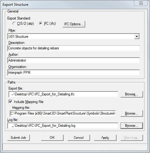
-
Select a tab to review the Export Structure dialog and the IFC Export Options dialog.
-
选择一个选项卡来查看“导出结构”对话框和“IFC 导出选项”对话框。
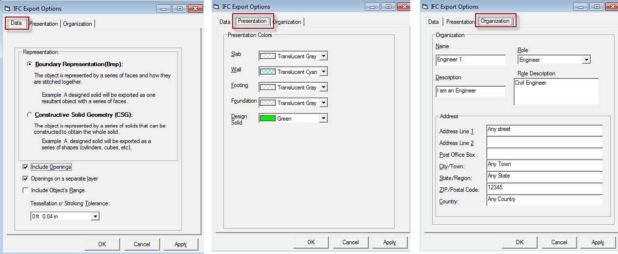
Auto-Connect for Import Structures
导入结构的自动连接
AutoConnect Explained in Detail
自动连接详细说明
AutoConnect is a new feature in Smart 3D, which allows an importing structure model to be automatically configured with frame connections at its corners or junction points. It establishes frame connections between existing members in the model using a predefined set of rules and tolerances.
自动连接是 Smart 3D 中的一项新功能,允许导入的结构模型在其角落或连接点处自动配置框架连接。它使用一组预定义的规则和公差在模型中的现有成员之间建立框架连接。
When structure is imported into Smart3D from another product using CIS/2, the member frame connections are set to "unsupported." Now, with the Member Autoconnect command, the software can set the most commonly needed frame connections automatically.
当使用 CIS/2 从另一个产品将结构导入 Smart3D 时,成员框架连接将设置为“不支持”。现在,使用 成员自动连接 命令,软件可以自动设置最常用的框架连接。
More About the AutoConnect Command
有关自动连接命令的更多信息
In this course, we will look at the Auto-Connect command. AutoConnect is a powerful feature that allows an imported structure model to be automatically configured with frame connections at the member systems' connection points.
在本课程中,我们将介绍自动连接命令。自动连接是一项强大的功能,它允许导入的结构模型在构件系统的连接点处自动配置框架连接。
The command establishes frame connections between existing member systems in the model using a predefined set of rules and tolerances.
该命令使用预定义的一组规则和公差在模型中现有的构件系统之间建立框架连接。
When a structure is imported into Smart 3D from another product using CIS/2, the member frame connections are set to unsupported.
当使用 CIS/2 将结构从其他产品导入 Smart 3D 时,构件框架连接将设置为不受支持。
Now, with the Member Autoconnect command, the software can set the most commonly needed frame connections automatically on the imported model.
现在,使用构件自动连接命令,软件可以在导入的模型上自动设置最常用的框架连接。
You can either let the software locate supporting objects automatically, or select them manually. Generally, when the software locates the supporting members, they must be within 25 centimeters of the supported member end. If more than one supporting candidate is found, built-in selection rules decide which supporting member to use, considering axis directions and relative position. Member type and cross-section size are ignored.
您可以让软件自动定位支撑对象,也可以手动选择它们。通常,当软件定位支撑构件时,它们必须在支撑构件端的 25 厘米范围内。如果找到多个支撑候选,内置选择规则将决定使用哪个支撑构件,同时考虑轴方向和相对位置。构件类型和横截面尺寸将被忽略。
If the user selects the supporting objects manually, the selection is simply based on the nearest member. This command only considers Frame Connections that are unsupported and have no supporting object or objects. Best results occur by using the Grid module first on columns, then Collinear if the columns are not continuous, then the Point On module for beams, and finally the End module for braces.
如果用户手动选择支撑对象,则选择仅基于最近的构件。此命令仅考虑不受支撑且没有支撑对象的框架连接。最佳效果是首先在柱上使用网格模块,然后如果柱不连续则使用共线模块,然后对梁使用点模块,最后对支撑使用末端模块。
Collinear requires the supporting member to be collinear with the supported member. In automatic mode, this module searches for collinear members successively.
共线要求支撑构件与被支撑构件共线。在自动模式下,此模块依次搜索共线构件。
If they are within 10 degrees of vertical, it locates only the top member so that the upper members use the lower members as their supporting object. Members with a horizontal orientation will prefer supporting objects with a vertical orientation or another horizontal orientation if both orientations are available. An example of this is two beams framing into a column.
如果它们在垂直方向的 10 度以内,则它仅定位顶部构件,以便上部构件使用下部构件作为其支撑对象。如果两个方向都可用,水平方向的构件将优先选择垂直方向或另一个水平方向的支撑对象。一个例子是两个梁构成一个柱子。
The beams will connect to the column, their vertical orientation, and not to each other, as in their horizontal orientation.
梁将连接到柱子(它们的垂直方向),而不是像水平方向那样彼此连接。
Members are considered vertical if they are within 10 degrees of vertical. Similarly, members are considered horizontal if they are within 10 degrees of horizontal.
如果构件在垂直方向的 10 度以内,则被视为垂直。同样,如果构件在水平方向的 10 度以内,则被视为水平。
The software determines the frame connection to use based on the geometry between the member selected and existing members in the model, similar to the By Rule connection option during placement. As a result, the automatic connection might select Axis-Along, Axis-Collinear, Axis-End, or Seated-Top.
软件根据所选构件与模型中现有构件之间的几何形状确定要使用的框架连接,类似于放置期间的按规则连接选项。因此,自动连接可能会选择轴沿、轴共线、轴末端或座顶。
Steps for Importing Third-Party Structure Models
导入第三方结构模型的步骤
There are three steps for properly importing third-party strucutue models into Smart 3D.
将第三方结构模型正确导入 Smart 3D 有三个步骤。
- Importing a structure model
- Creating a grid system
-
Using AutoConnect
-
导入结构模型
- 创建网格系统
- 使用自动连接
Demonstration—Importing a Structure Model into Smart 3D
演示 — 将结构模型导入 Smart 3D
This video demonstrates importing a structure from a CIS/2 file. The overall workflow for importing a structure is:
此视频演示了如何从 CIS/2 文件导入结构。导入结构的总体工作流程如下:
-
Import the structural model. 2. Define a grid system for the imported model. 3. Use AutoConnect to define the needed frame connections.
-
导入结构模型。2. 为导入的模型定义网格系统。3. 使用 AutoConnect 定义所需的框架连接。
We'll start by creating a new workspace filter. Create a new session file and define your workspace with the U01 coordinate system.
我们将从创建一个新的工作区过滤器开始。创建一个新的会话文件并使用 U01 坐标系定义您的工作区。
Select the U01_CS from the Workspace Explorer and Hide it. Make sure the Active Permission Group is set to Structural.
从工作区资源管理器中选择 U01_CS 并将其隐藏。确保活动权限组设置为结构。
Right-click on the Plant Node, select New System, New Structure System. Enter FWStructure for the name. Select OK to create the system.
右键单击工厂节点,选择新系统、新结构系统。输入 FWStructure 作为名称。选择确定以创建系统。
Select File, Import, Structure, CIS/2. On the Import Structure dialog, set System to FWStructure. Set Coordinate System to Global.
选择文件、导入、结构、CIS/2。在导入结构对话框中,将系统设置为 FWStructure。将坐标系设置为全局。
For the Import File, select FWPSampleData.stp file that is delivered with the software. Select the Include Mapping File option.
对于导入文件,选择随软件提供的 FWPSampleData.stp 文件。选择包含映射文件选项。
Select the FWP AISC Master Physical Map.xml file. Define a log file name and location. Select Import and the "Use no default member cross sections" option.
选择 FWP AISC Master Physical Map.xml 文件。定义日志文件名称和位置。选择导入和“不使用默认成员横截面”选项。
After the import is complete, click View Log to review the log file for errors and mapping issues.
导入完成后,单击查看日志以查看日志文件中的错误和映射问题。
Click Cancel to close the Import Structure dialog. Then Fit the view. In this video we imported a structural model from a CIS/2 file into the model.
单击取消以关闭导入结构对话框。然后调整视图。在此视频中,我们将 CIS/2 文件中的结构模型导入到模型中。
Demonstration—Creating a Grid System for the Imported Structure
演示 — 为导入的结构创建网格系统
This video demonstrates creating a grid system for our imported structure. Modify your workspace properties and make sure the U01 and FWStructure are in your workspace. Before we can create the grid system, we need to do some investigation to figure out the plane locations that we'll need. Set the Locate Filter to Member Systems. Decide where you want the grid system's origin and select that column.
此视频演示了如何为导入的结构创建网格系统。修改您的工作区属性,并确保 U01 和 FWStructure 位于您的工作区中。在创建网格系统之前,我们需要进行一些调查,以确定所需的平面位置。将定位过滤器设置为成员系统。确定网格系统的原点,然后选择该列。
We'll use the column's start elevation as our grid system's origin. Note the column's end elevation too, because we'll need an elevation plane at that height.
我们将使用列的起始高程作为网格系统的原点。还请注意列的终止高程,因为我们需要在该高度的标高平面。
Select a member in the X direction. Note the End East location to get the distance to use for the grid plane spacing. Select a member in the Y direction to get the plane spacing in that direction.
选择 X 方向上的成员。注意东端位置以获取用于网格平面间距的距离。选择 Y 方向上的成员以获取该方向的平面间距。
Continue to select members noting the needed elevation planes.
继续选择成员,注意所需的标高平面。
Now switch to the Grids task. Select the Grid Wizard command on the vertical toolbar. On the Create Coordinate System dialog, type a name for the new coordinate system. Make the parent System CS, and choose New Coordinate system.
现在切换到网格任务。选择垂直工具栏上的网格向导命令。在创建坐标系对话框中,键入新坐标系的名称。建立父系统 CS,然后选择新坐标系。
For Grid Type, set Grids, and Rectangular. Axis for Bearing will be North, and Bearing will be N 0.00 degrees East.
对于网格类型,设置网格和矩形。方位轴为北,方位为东经 0.00 度。
With Origin, set the Reference Coordinate System to Global. Set East, North, and Elevation to be 0 feet 0 inches (the bottom elevation of that column we first selected). Select Next. On the Create Elevation Planes dialog, define the elevation planes that you noted during the investigation.
对于原点,将参考坐标系设置为全局。将东、北和高程设置为 0 英尺 0 英寸(我们首先选择的该列的底部高程)。选择下一步。在“创建高程平面”对话框中,定义您在调查期间记录的高程平面。
Select Next on the dialog to open the Create X Planes window. Define 5 planes 20 feet apart.
在对话框中选择下一步以打开“创建 X 平面”窗口。定义 5 个相距 20 英尺的平面。
Select Next to open the Y-Planes dialog. Define 2 planes 15 feet apart. Select Next. Verify that everything is correct and then select Finish. The grid system should place on the imported model. The rulers can be turned off as needed.
选择下一步以打开 Y 平面对话框。定义 2 个相距 15 英尺的平面。选择下一步。验证所有信息是否正确,然后选择完成。网格系统应放置在导入的模型上。可以根据需要关闭标尺。
Refer to the Grids course for detailed information about using the Grids Wizard.
有关使用网格向导的详细信息,请参阅网格课程。
Demonstration—Using AutoConnect for Imported Structures
演示 — 使用自动连接导入结构
This video demonstrates using the Autoconnect command to add the appropriate frame connections to an imported structure.
此视频演示如何使用自动连接命令将适当的框架连接添加到导入的结构。
Best results occur by using the Grid connection method first on columns, then Collinear if the columns are not continuous, then the Point On connection method for beams, and finally the End connection method for braces.
最佳效果是首先对柱使用网格连接方法,然后如果柱不连续则使用共线,然后对梁使用点连接方法,最后对支撑使用端部连接方法。
In the Structure task, Select the Member Autoconnect command on the vertical toolbar. Select each column located in the grid system.
在结构任务中,选择垂直工具栏上的构件自动连接命令。选择位于网格系统中的每个柱。
Set the Connection Method to Collinear, and then select Finish again. The upper connections at the splice point are set to Axis End and the lower connection are left unsupported.
将连接方法设置为共线,然后再次选择完成。拼接点处的上部连接设置为轴端,下部连接不受支撑。
Set the Connection Method to Grid, and select Finish. Notice here that the top and bottom frame connections of the columns are automatically connected to the grid intersections. Set the locate filter to Frame Connections and select a column's top frame connection.
将连接方法设置为网格,然后选择完成。请注意,柱的顶部和底部框架连接会自动连接到网格交叉点。将定位过滤器设置为框架连接,然后选择柱的顶部框架连接。
It should be unsupported, but connected to the Grid intersection. Select the top frame connection at the splice.
它应该不受支撑,但连接到网格交叉点。选择拼接处的顶部框架连接。
It should be an axis-end connection to the top of the lower column. The easiest way to select all the beams is to select Tools, Select By Filter and create a filter for the imported beams. Name the filter Imported Beams, select the FW Structure folder from the System tab, and use the Properties tab to set the type to Beam.
它应该是轴端到下柱顶部的连接。选择所有梁的最简单方法是选择“工具”,“按过滤器选择”,然后为导入的梁创建一个过滤器。将过滤器命名为“导入的梁”,从“系统”选项卡中选择“FW 结构”文件夹,然后使用“属性”选项卡将类型设置为“梁”。
Select OK. Now select the new filter in the Select Filter window and select OK. Only the imported beams should highlight.
选择“确定”。现在在“选择过滤器”窗口中选择新过滤器,然后选择“确定”。只有导入的梁才会突出显示。
Select the Member Autoconnect command with the beams selected. Set the Connection Method to Point On, and select Finish again.
在选定梁的情况下选择“构件自动连接”命令。将“连接方法”设置为“点”,然后再次选择“完成”。
The beams are automatically connected. Right-click to exit the command. Let's verify that everything worked out correctly.
梁会自动连接。右键单击退出命令。让我们验证一切是否正确运行。
Select one of the beam frame connections. You should note that the beam is connected to both the column and elevation plane as recommended in the member placement exercises. Right-click to unselect the frame connection. We are now going to connect the braces.
选择其中一个梁框架连接。您应该注意到,梁连接到柱和立面平面,正如构件放置练习中所建议的那样。右键单击取消选择框架连接。我们现在要连接支架。
Select the braces. Then select the Member Autoconnect command again. Set the Connection Method to End, check the Extend option to have the software automatically extend or shorten the selected members to make the required connection possible. Select Finish. The braces are connected automatically.
选择支架。然后再次选择“构件自动连接”命令。将连接方法设置为结束,选中延伸选项以使软件自动延伸或缩短选定的构件,以实现所需的连接。选择完成。支架自动连接。
Right-click to exit the command. Select one of the top brace frame connections to verify the connection. You should note that the brace is connected to both the column and beam with a Vertical Corner Brace as recommended in your member placement exercises.
右键单击退出命令。选择顶部支架框架连接之一以验证连接。您应该注意到,支架使用垂直角撑连接到柱和梁,正如构件放置练习中所建议的那样。
Summary
总结
In this course, you were introduced to a new command in Smart 3D—AutoConnect.
在本课程中,我们向您介绍了 Smart 3D 中的新命令 — AutoConnect。
You learned how to use the AutoConnect command to configure a third-party structure model for use in Smart 3D.
您学习了如何使用 AutoConnect 命令配置第三方结构模型以供在 Smart 3D 中使用。
There are three steps for properly importing third-party structure models into Smart 3D.
将第三方结构模型正确导入 Smart 3D 有三个步骤。
- Importing a structure model
- Creating a grid system
-
Using AutoConnect
-
导入结构模型
- 创建网格系统
- 使用 AutoConnect
Overall Summary
整体总结
First, let's take a look at what design objects that you can place in the Structure task.
首先我们先来了解您可以在结构任务中放置哪些设计对象。
The structural member design is divided into two design objects, the member system and the member part. Member systems are logical collections of member parts that maintain the design basis and physical alignment of the member parts for analysis, design, and manufacturing. For example, in vertical cross-bracing, typically one of the vertical braces is split into two parts so that it does not interfere with the other vertical brace in the cross. The member system for that split vertical brace maintains the co-linear alignment of the two parts when you move either outside corner of the vertical brace. Member parts are children of a standard member system and represent the physical parts in the model. Member parts connect logically to other member parts using assembly connections.
结构构件设计分为两个设计对象,即构件系统和构件部件。构件系统是构件部件的逻辑集合,可保持构件部件的设计基础和物理对齐,以进行分析、设计和制造。例如,在垂直交叉支撑中,通常将其中一个垂直支撑分成两部分,以便它不会干扰交叉中的另一个垂直支撑。当您移动垂直支撑的任一外角时,该分割垂直支撑的构件系统会保持两个部分的共线对齐。构件部件是标准构件系统的子项,表示模型中的物理部件。构件部件使用装配连接逻辑地连接到其他构件部件。
A member part can be split into multiple member parts, and you can assign different materials, section sizes, and cardinal points to each member part. You can also trim the member part, if required. The Place Linear Member System command creates the member system, the member part, and the frame connections at the same time. A member split divides a member system into a set of continuous member parts that move as a single entity. This splitting is useful when you want to resolve the interference between two intersecting structural objects, such as a pair of cross braces, or when you want to split the columns in your model at certain elevations. You can split member systems at another member system, at a point along the member system, a grid plane, an elevation plane, deck, bulkhead, or plate system. A linear member is a member system consisting of a standard section from the Catalog projected along a line defined by two points.
可以将一个构件部分拆分为多个构件部分,并且可以为每个构件部分分配不同的材料、截面尺寸和基点。如果需要,还可以修剪构件部分。放置线性构件系统命令可同时创建构件系统、构件部分和框架连接。构件拆分将构件系统拆分为一组连续的构件部分,这些构件部分可作为单个实体移动。当您想要解决两个相交结构对象(例如一对交叉支撑)之间的干扰,或者想要在特定高度拆分模型中的柱时,此拆分非常有用。您可以在另一个构件系统、构件系统沿线的某个点、网格平面、高程平面、甲板、舱壁或板系统拆分构件系统。线性构件是由目录中的标准截面沿由两点定义的线投影组成的构件系统。
A curved member is a member system consisting of a standard section from the Catalog projected along a curve. The curve can be defined by several sketching options including the most common, Arc by Three Points. A frame connection defines the connection and positioning of the member systems relative to each other, grid lines, and surfaces of other objects, or simply to a point in space. Each end of a member system can have a different frame connection type.
弯曲构件是由目录中的标准截面沿曲线投影组成的构件系统。可以通过多种草图选项定义曲线,包括最常见的“三点圆弧”。框架连接定义构件系统相对于彼此、网格线和其他对象的表面或空间中某个点的连接和定位。构件系统的每一端可以具有不同的框架连接类型。
They are created as you place members. When placing a member, you select the type of frame connection that represents the intent of engineering positioning or you can let the system select the appropriate frame connection using the By Rule option.
它们是在您放置构件时创建的。放置构件时,您可以选择代表工程定位意图的框架连接类型,也可以让系统使用“按规则”选项选择适当的框架连接。
For example, the seated frame connection positions the supported member on top or bottom of the supporting member regardless of the cardinal points that were used to place the members. An assembly connection adds or removes material from the member and creates the additional parts needed for the physical joint. It is a design object that controls the creation and placement of other design objects. The current default Catalog provides assembly connection types that simply approximate the final connection by creating trims, base plates, and gusset plates as necessary. You must do the detailed structural connection design external to Smart 3D.
例如,无论用于放置构件的基点是什么,固定框架连接都会将支撑构件定位在支撑构件的顶部或底部。装配连接会从构件中添加或移除材料,并创建物理接头所需的其他零件。它是一个设计对象,用于控制其他设计对象的创建和放置。当前默认目录提供的装配连接类型只是通过根据需要创建装饰、底板和角撑板来近似最终连接。您必须在 Smart 3D 之外进行详细的结构连接设计。
The assembly connection recalculates automatically when you edit the member's position or size. You apply the assembly connections late in the design cycle to keep the model lighter during frequent editing of the frame design. A slab is used to represent any type of constant-thickness solid such as actual floor slabs, steel grating, steel plate, and roofing. The model geometry is a constant-thickness solid, but properties can define layers of different materials for reports. The default structure Catalog defines several different types.
当您编辑构件的位置或尺寸时,装配连接会自动重新计算。您可以在设计周期的后期应用装配连接,以便在频繁编辑框架设计时保持模型更轻。板用于表示任何类型的恒定厚度实体,例如实际楼板、钢格栅、钢板和屋顶。模型几何体是恒定厚度实体,但属性可以为报告定义不同材料的层。默认结构目录定义了几种不同的类型。
You place a slab by selecting or defining a plane and a boundary. Several methods are provided for defining the plane and the boundary. A wall is a cross-section projected along a planar path and optionally bounded or trimmed at the top by selected surfaces. The model geometry is a solid, but properties can define layers of different materials for reports. The cross-section can be rectangular for typical constant thickness walls or can have different shapes as defined in the Catalog. For example, retaining walls can have a nonrectangular cross-section.
您可以通过选择或定义平面和边界来放置板。提供了几种定义平面和边界的方法。墙是沿平面路径投影的横截面,可以选择在顶部由选定的表面限制或修剪。模型几何体是实体,但属性可以为报告定义不同材料的层。横截面可以是典型的恒定厚度墙的矩形,也可以具有目录中定义的不同形状。例如,挡土墙可以具有非矩形横截面。
You can define the path in the 2D sketching environment or by drawing directly in the 3D model. You choose how the cross-section is positioned relative to the path by cardinal points defined on the cross-section shape. An opening can be made in a slab, wall, or member. You define the shape of the opening by selecting boundaries, sketching the opening outline, or placing a predefined 2D opening shape from the Catalog. You can control the depth of the opening to create a fully penetrating hole or a recessed opening. The default equipment Catalog provides several types of doors and windows under the Architectural node.
您可以在 2D 草图环境中定义路径,也可以直接在 3D 模型中绘制路径。您可以通过在横截面形状上定义的基本点来选择横截面相对于路径的定位方式。可以在板、墙或构件上开孔。您可以通过选择边界、绘制开口轮廓或从目录中放置预定义的 2D 开口形状来定义开口的形状。您可以控制开口的深度以创建完全穿透的孔或凹陷的开口。默认设备目录在“建筑”节点下提供了几种类型的门窗。
When you place a door or window using the Place Equipment command, the required rough opening is also automatically created in the wall or slab. A footing is used to transfer the loads of a column to the ground or sub-structure and to provide mounting stability for the supported column and can be placed before or after columns are placed in the model. The software creates a relationship between the footing and the member end to which the footing connects. There are two types of footings that you can place: single and combined. Single footings create a one-to-one relationship between the column and the footing. Combined footings create a many-to-one relationship between multiple columns and a single footing. A typical footing is comprised of: A base that supports one or more piers. Some footings for light-weight structures, such as a light pole, do not have a base. A pier that rests on the base and supports the grout layer.
当您使用“放置设备”命令放置门或窗时,所需的粗糙开口也会自动在墙或板上创建。基础用于将柱的负载转移到地面或子结构,并为支撑的柱提供安装稳定性,可以在将柱放置在模型中之前或之后放置。软件会在基础和基础连接的构件端之间创建关系。您可以放置两种类型的基础:单一基础和组合基础。单一基础在柱子和基础之间建立一对一关系。组合基础在多个柱子和一个基础之间建立多对一关系。典型的基础由以下部分组成:支撑一个或多个墩子的底座。某些轻型结构(例如灯杆)的基础没有底座。墩子,位于底座上并支撑灌浆层。
Some footings do not have a pier in which case the grout is put directly on the base. A grout layer that rests on the pier and supports the base plate. A base plate that rests on the grout layer and is welded to the supported column. An equipment foundation can be composed of actual structural members with fabrication identities or just geometry sufficiently detailed for general arrangement drawings. The behavior depends on the type of equipment foundation chosen from the Catalog. You place a foundation relative to existing equipment. The height of the foundation can be defined by selecting a supporting surface or plane or by entering the foundation dimensions. Stair and ladder placements generate geometry sufficiently detailed for general arrangement drawings and for participation in interference detection. They do not create separate parts with fabrication identities and properties.
某些基础没有墩子,在这种情况下,灌浆直接放在底座上。灌浆层,位于墩子上并支撑底板。底板,位于灌浆层上并焊接到支撑柱子上。设备基础可以由具有制造标识的实际结构构件组成,也可以仅由足够详细的几何图形组成,以用于总体布置图。行为取决于从目录中选择的设备基础类型。您可以相对于现有设备放置基础。可以通过选择支撑表面或平面或输入基础尺寸来定义基础的高度。楼梯和梯子的放置会生成足够详细的几何图形,用于总体布置图和参与干涉检测。它们不会创建具有制造标识和属性的单独零件。
However, the parameters of the design object can be used along with standards to drive useful material reports. You place stairs and ladders relative to a bottom plane, top edge, and an offset from a reference edge or surface. A handrail is, by default, a symbol based object that generates geometry sufficiently detailed for general arrangement drawing and for the participation in interference detection. It does not create separate parts with fabrication identities and properties. You do have the option to convert the symbol based handrail to a designed handrail. Converting a handrail decomposes the handrail symbol to individual structural members for each post and rail. You can place a handrail by defining a path by points or by selecting members. The Place Equipment command is available in the Structure task and is used to place predefined constructions from the Catalog. You can place any standard equipment from the Catalog using this command.
但是,设计对象的参数可以与标准一起使用,以驱动有用的材料报告。您可以相对于底部平面、顶部边缘和与参考边缘或表面的偏移来放置楼梯和梯子。默认情况下,扶手是基于符号的对象,可生成足够详细的几何图形,用于总体布置图和参与干涉检测。它不会创建具有制造标识和属性的单独零件。您可以选择将基于符号的扶手转换为设计的扶手。转换扶手会将扶手符号分解为每个柱子和扶手的单独结构构件。您可以通过定义点路径或选择构件来放置扶手。结构任务中的“放置设备”命令可用,用于放置目录中的预定义结构。您可以使用此命令放置目录中的任何标准设备。
For example, you can place predefined manholes and catch basins while in the Structure task. You can also place designed equipment, designed equipment components, doors, windows, and designed solids in the Structure task. If you want to export your structure, the File, Export, Structure command exports the structural physical model to the CIS/2 or IFC formats. With IFCs, you can export concrete slabs, walls, structural systems, openings on slabs or walls, footings, equipment foundations, and designed equipment having an equipment classification of civil elements or structural elements. Linear or Curved members cannot be exported to IFC.
例如,您可以在结构任务中放置预定义的检修孔和集水池。您还可以在结构任务中放置设计的设备、设计的设备组件、门、窗和设计的实体。如果要导出结构,文件、导出、结构命令会将结构物理模型导出为 CIS/2 或 IFC 格式。使用 IFC,您可以导出混凝土板、墙、结构系统、板或墙上的开口、基础、设备基础和具有土木元素或结构元素设备分类的设计设备。线性或曲线构件不能导出到 IFC。
For these structural component types, you must use CIS/2. Using CIMSteel Integration Standard file format (CIS/2) from the Structure task, you can export as well as import a structure. The File, Import Structure command imports a CIS/2 file into your model. This command recognizes global user identities (GUIDs) to uniquely identify objects and manage the electronic exchange with the other software package. The CIS/2 file contains all the necessary physical data to allow third-party software, such as a detailing application, to import the structure.
对于这些结构组件类型,您必须使用 CIS/2。使用结构任务中的 CIMSteel 集成标准文件格式 (CIS/2),您可以导出和导入结构。文件、导入结构命令将 CIS/2 文件导入到您的模型中。此命令识别全局用户身份 (GUID) 以唯一地标识对象并管理与其他软件包的电子交换。 CIS/2 文件包含所有必要的物理数据,以允许第三方软件(例如详细应用程序)导入结构。
---Day4 Continue---