
Civil
约 11355 个字 预计阅读时间 38 分钟
---Day4---
Overview
概述
Trenches are commonly used in all industries as a conduit for cables and pipes, and for the rapid evacuation of surface water or chemical spills.
沟渠在所有行业中都广泛用于电缆和管道的管道,以及快速排出地表水或化学品泄漏。
A trench is usually made of concrete that is pre-cast or cast-in-place. It can be covered with a solid slab or steel grating that is flush with the adjoining surface, or it could be considered open ditches.
沟渠通常由预制或现浇混凝土制成。它可以用与相邻表面齐平的实心板或钢格栅覆盖,也可以被视为明渠。
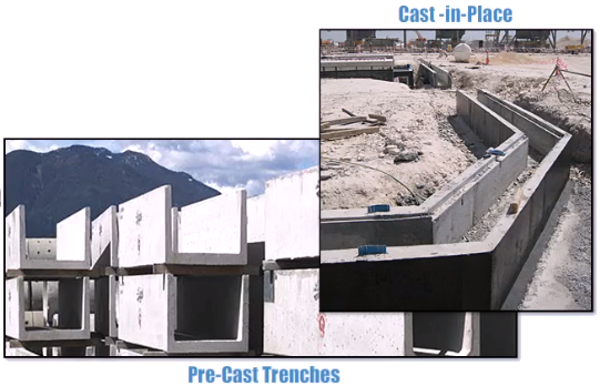
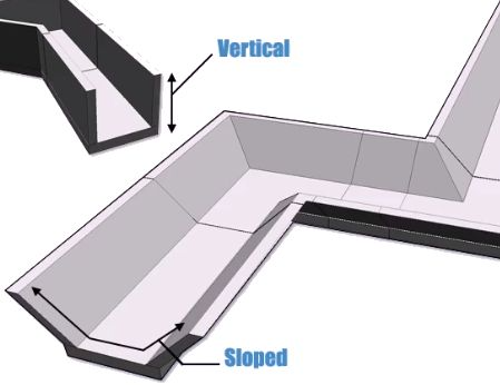
Trenches have vertical walls while ditches typically have sloped walls.
战壕的壁是垂直的,而壕沟的壁通常是倾斜的。
The Smart 3D Civil task environment enables you to place and modify trenches, ditches, and utility tunnels of varying cross sections using familiar Smart 3D workflows. Let's continue to take a closer look!
Smart 3D Civil 任务环境使您能够使用熟悉的 Smart 3D 工作流程放置和修改不同横截面的沟渠、沟渠和公用设施隧道。让我们继续仔细看看!
Civil Task Environment
土木工程任务环境
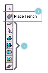
To access the Civil environment, select Task > Civil. The Place Trench command is the starting point to dynamically place and modify trenches.
要访问土木工程环境,请选择“任务”>“土木工程”。放置沟槽命令是动态放置和修改沟槽的起点。
The Place Trench command uses the same 3D path placement methods you are familiar with using Smart 3D's Structure and Equipment & Furnishings commands. Smart 3D integrates new trench objects with the existing tools for modeling catch basins, manholes, roadways, footings and equipment foundations.
放置沟槽 命令使用与您熟悉的 Smart 3D 结构和设备与家具命令相同的 3D 路径放置方法。Smart 3D 将新的沟槽对象与现有工具集成,用于建模集水池、人孔、道路、地基和设备基础。
Activating the Place Trench command also opens the Place Trench ribbon.
激活 放置沟槽 命令还会打开 放置沟槽 功能区。
These commands are also available in the Structure or Equipment & Furnishings tasks. This makes trench design easier by using familiar tools.
这些命令也可在结构或设备与家具任务中使用。使用熟悉的工具,沟槽设计变得更加容易。
 | Place Slab - Places slabs, plates, and grates in the model. |
 | Place Wall - Places a wall in the model. |
 | Place Designed Equipment - Places designed equipment types that have been defined in the reference data. |
 | Place Designed Equipment Component - Places designed equipment components that have been defined in the reference data. |
 | Place Designed Solid - Creates customized solids and equipment using shapes that add material to or subtract material from the designed solid. |
 | Place Shape - Adds additional shapes or equipment objects to an existing designed equipment type. The icon displayed on the toolbar is the icon of the last shape selected from the palette. |
 | Place Imported Shape From File - Adds geometry to a designed equipment object that was modeled with solid modeling software and saved to an SAT or MicroStation DGN file format. |
 | Place Opening - Places openings (holes) in slabs, walls, and linear member systems. |
System Tab
系统选项卡
The following Civil objects appear on the System tab of the Workspace Explorer:
工作区浏览器的“系统”选项卡上显示以下 Civil 对象:
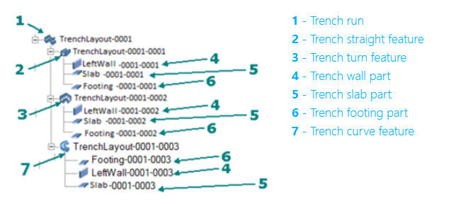
 Trench Run
A trench run contains the top-level properties for a trench, including the trench type, trench cross-section, elevations, and slopes. The trench run also defines the path of the trench.
沟槽管线包含沟槽的顶级属性,包括沟槽类型、沟槽横截面、高程和坡度。沟槽管线还定义了沟槽的路径。
 Trench Straight Feature
A trench straight feature contains the properties of a straight section of the trench and inherits properties from the parent trench run. You can manually change some properties, such as the trench width, to modify the dimensions of the individual feature.
沟槽直线特征包含沟槽直线部分的属性,并继承了父沟槽的属性。您可以手动更改某些属性(例如沟槽宽度)以修改单个特征的尺寸。
 Trench Curve Feature
A trench curve feature contains the properties of a curve section of the trench and inherits properties from the parent trench run. You can manually change some properties, such as the trench width, to modify the dimensions of the individual feature.
沟槽曲线特征包含沟槽曲线部分的属性,并继承了父沟槽的属性。您可以手动更改某些属性(例如沟槽宽度)以修改单个特征的尺寸。
 Trench Turn Feature
A trench turn feature contains the properties of a turn section of the trench and inherits properties from the parent trench run. You can manually change some properties, such as corner chamfers.
沟槽转弯特征包含沟槽转弯部分的属性,并继承了父沟槽的属性。您可以手动更改某些属性,例如拐角倒角。
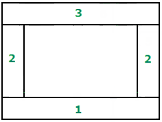 | 1 - Trench footing part 2 - Trench wall part 3 - Trench slab part |
 Trench Footing Part
Contains the properties of the bottom footing of a trench.
包含沟槽底部基础的属性。
 Trench Slab Part
Contains the properties of the top slab of a trench.
包含沟槽顶板的属性。
 Trench Wall Part
Contains the properties of the left or right wall of a trench.
包含沟槽左壁或右壁的属性。
Assembly Tab
装配选项卡
Trench Footing Part
沟槽基础部件
Contains the properties of the bottom footing of a trench.
包含沟槽底部基础的属性。
Trench Slab Part
沟槽板部件
Contains the properties of the top slab of a trench.
包含沟槽顶板的属性。
Trench Wall Part
沟槽壁部件
Contains the properties of the left or right wall of a trench.
包含沟槽左壁或右壁的属性。
Demonstration - Basic Trench Routing and Modification Workflows
演示 - 基本沟槽布线和修改工作流程
The Place Trench command uses the 3D path placement method common to other Smart 3D structure and equipment commands. Here's the recommended, basic workflow:
“放置沟槽”命令使用与其他 Smart 3D 结构和设备命令通用的 3D 路径放置方法。以下是推荐的基本工作流程:
- Civil objects are placed in the model using information defined in the Civil reference data. Review the delivered reference data using the Catalog task. You can create and edit customized civil reference data rules, symbols, and Microsoft Excel workbooks.
- After the reference data is customized to suit your needs, consider going to the Systems and Specifications task to define the systems that you want in your model. While not absolutely required that you create your systems first, doing so keeps you from having to edit your objects after placement to assign them to the correct system.
- Create your elevations and grids using the Grids task before placing civil objects.
-
Use the Place Trench command to add the objects in your model.
-
使用土木工程参考数据中定义的信息将土木工程对象放置在模型中。使用目录任务查看交付的参考数据。您可以创建和编辑自定义的土木工程参考数据规则、符号和 Microsoft Excel 工作簿。
-
在根据您的需要自定义参考数据后,请考虑转到系统和规范任务来定义您想要在模型中使用的系统。虽然您不一定需要先创建系统,但这样做可以让您不必在放置后编辑对象以将它们分配给正确的系统。
-
在放置土木工程对象之前,使用网格任务创建高程和网格。
-
使用“放置沟槽”命令将对象添加到模型中。
Demonstration - Basic Trench Routing——【操作】常规放置沟渠和管道Trench
演示 - 基本沟槽布线
In this demonstration, we will place trenches in the U12 workspace, and then see the properties that can be edited.
在此演示中,我们将在 U12 工作区中放置沟槽,然后查看可以编辑的属性。
In the PinPoint ribbon, we have the U12_T coordinate system selected and a grid is already in place for alignment.
在 PinPoint 功能区中,我们选择了 U12_T 坐标系,并且已经设置了网格以进行对齐。
To get started, select the Civil task, and then select Place Trench. Select the trench type and enter a name. Keep in mind that you cannot change the type after placement.
首先,选择 Civil 任务,然后选择 Place Trench。选择沟槽类型并输入名称。请记住,放置后无法更改类型。
Select values for the Cardinal Point, Placement Method, and Cross-Section. Select Path and use the grid intersection to set start and end points for the trench run.
选择基点、放置方法和横截面的值。选择路径并使用网格交点设置沟槽运行的起点和终点。
Select Finish to complete the path. Select Finish again to place the trench. Select the trench, and then select Properties.
选择“完成”以完成路径。再次选择“完成”以放置沟槽。选择沟槽,然后选择“属性”。
Although you cannot change the trench type, you can edit the dimensional properties of the trench. Select the Cross-Section tab, and then select Show Dimension Legend.
虽然无法更改沟槽类型,但可以编辑沟槽的尺寸属性。选择“横截面”选项卡,然后选择“显示尺寸图例”。
You can now review the trench properties available for the selected Cross-Section. Edit one or more of the dimensional properties as needed.
现在,您可以查看所选横截面可用的沟槽属性。根据需要编辑一个或多个尺寸属性。
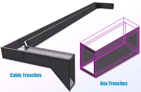
Now let's repeat the same process to place a box trench. Select the Place Trench command, and then select the PipeTrench_Box for the Type.
现在让我们重复相同的过程来放置箱形沟槽。选择“放置沟槽”命令,然后选择“类型”为 PipeTrench_Box。
Enter a name for the trench. For the Cross-Section, select Box. Select Path and again use the grid to align and place the trench.
输入沟槽的名称。对于“横截面”,选择“箱形”。选择“路径”,然后再次使用网格对齐并放置沟槽。
Select Finish twice to end the path and place the trench. The box trench displays and you can open Properties to edit any required dimensions.
选择“完成”两次以结束路径并放置沟槽。显示箱形沟槽,您可以打开“属性”以编辑任何所需的尺寸。
On the Cross-Section tab, select Show Dimension Legend to review the dimensions.
在“横截面”选项卡上,选择“显示尺寸图例”以查看尺寸。
Points to Remember
要点
The Smart 3D Civil task enables you to work with trenches, ditches, and utility tunnels using familiar Smart 3D workflows and vertical toolbar commands.
Smart 3D Civil 任务使您能够使用熟悉的 Smart 3D 工作流和垂直工具栏命令处理沟渠、沟渠和公用设施隧道。
The Civil task environment provides tools and familiar commands from Common and Equipment & Furnishings tasks for easier and more efficient work.
Civil 任务环境提供了来自 Common 和 Equipment & Furnishings 任务的工具和熟悉的命令,使工作更轻松、更高效。
Basic trench routing and modification workflows start with civil objects defined in the Civil reference data. Review the delivered reference data using the Catalog task. After trench placement, you can edit an existing trench’s dimensional properties.
基本沟渠布线和修改工作流从 Civil 参考数据中定义的土木工程对象开始。使用 Catalog 任务查看交付的参考数据。放置沟渠后,您可以编辑现有沟渠的尺寸属性。
When planning your trench design, consider going to the Systems and Specifications task to define the required systems so that you do not have to edit your objects after placement to assign them to the correct system. We also recommend that you place grids before placing a trench.
规划沟渠设计时,请考虑转到“系统和规范”任务来定义所需的系统,这样您就不必在放置后编辑对象以将它们分配给正确的系统。我们还建议您在放置沟渠之前放置网格。
Place Piping Trenches & Drainage Ditches
放置管道沟和排水沟
Overview
概述
The Place Trench command allows the dynamic placement and modification of trenches through a potentially complex sequence of changing elevations, transitions, and branching requirements.
“放置沟”命令允许通过一系列可能复杂的高程、过渡和分支要求变化序列动态放置和修改沟渠。
Demonstration—Place a Piping Trench with a Bottom Slope
演示 - 放置具有底部坡度的管道沟

In this demonstration, we are using the U12 workspace with the U12_CS coordinate system. We will use the grid intersections as a guide to change the elevation as we place the trench.
在此演示中,我们使用带有 U12_CS 坐标系的 U12 工作区。我们将使用网格交叉点作为指南,在放置沟渠时更改高程。
The pre-defined grid has planes below grade at 1 foot intervals to show a slope. Select the Place Trench command.
预定义的网格在 1 英尺间隔内具有低于地面的平面以显示坡度。选择“放置沟渠”命令。
Enter a name and set the options to define your trench run. Select the Path command and then select the grid intersection to start trench placement.
输入名称并设置选项以定义您的沟渠。选择“路径”命令,然后选择网格交叉点以开始放置沟渠。
Place path points and change elevation using the grid to sketch the trench run. Click Finish to complete the path.
放置路径点并使用网格更改高程以绘制沟渠。单击“完成”以完成路径。
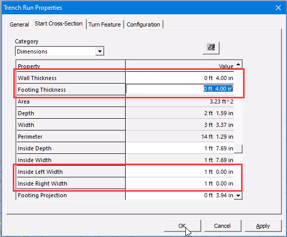
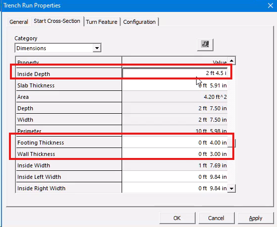
Select the Properties button, and then click the Start Cross-Section tab. Set any required parameters such as Wall and Footing Thickness.
选择“属性”按钮,然后单击“开始横截面”选项卡。设置任何所需参数,例如墙和基础厚度。
Click Finish again to place the Trench. You can change the view to check the elevation changes and bottom slope.
再次单击“完成”以放置沟渠。您可以更改视图以检查高程变化和底部坡度。
Right-click to end the edit process. Now set your Locate Filter so that you can select a feature or part that make up your trench run.
右键单击以结束编辑过程。现在设置您的定位过滤器,以便您可以选择构成沟槽的特征或部分。
Select each object and then select Properties to edit values such as width or thickness.
选择每个对象,然后选择属性以编辑宽度或厚度等值。
Demonstration—Place a Piping Trench Without a Slope
演示 — 放置无坡度的管道沟槽
In this demonstration, we are using the U12 Workspace with the U12 coordinate system. We will place a trench run without a slope and add branches to the run.
在此演示中,我们使用 U12 工作区和 U12 坐标系。我们将放置无坡度的沟槽,并在沟槽中添加分支。
The trench run will consist of a series of sections to separate the trench into multiple trench features. The separate features enable easier modification later on.
沟槽将由一系列部分组成,将沟槽分成多个沟槽特征。单独的特征使以后的修改更加容易。
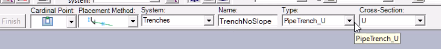
For exact positioning, we will place each trench section using the East, North, and Elevation coordinates. Because there is no slope, a grid is not needed for guidelines. To get started, let’s activate PinPoint.
为了精确定位,我们将使用东、北和高程坐标放置每个沟槽部分。由于没有坡度,因此不需要网格作为指导。首先,让我们激活 PinPoint。
Select Target to Origin, and then select Place Trench. Define settings for the trench, and then select Path to start sketching the Trench path.
选择目标到原点,然后选择放置沟槽。定义沟槽的设置,然后选择路径以开始绘制沟槽路径。
Enter coordinate values, and then left click anywhere in the graphic view to start the path at the coordinates. Enter a length for each section as you move along the path.
输入坐标值,然后在图形视图中的任意位置单击鼠标左键,以从坐标处开始路径。沿路径移动时输入每个部分的长度。
Enter coordinates to place a turn in the trench run. Select Finish to complete the path, and again to place the trench.
输入坐标以在沟槽中放置转弯。选择完成以完成路径,然后再次放置沟槽。
We will add branches to the north-east end of the trench. Let’s zoom in for a closer view. Select Place Trench again and keep the same settings.
我们将在沟槽的东北端添加分支。让我们放大以近距离查看。再次选择“放置沟槽”并保持相同的设置。
Select Path and then enter the coordinate values for the placement. Left click on the path of the existing run. For this example, we will enter a North coordinate value for the branch.
选择“路径”,然后输入放置的坐标值。左键单击现有运行的路径。在此示例中,我们将输入分支的北坐标值。
Select in the graphic view to place the point. Select Finish to complete the path, and then select again to place the trench branch.
在图形视图中选择以放置点。选择“完成”以完成路径,然后再次选择以放置沟槽分支。
To add two more branches, select Place Trench again, and repeat the previous steps. Remember to use the sketching icons to help with alignment and placement.
要添加另外两个分支,请再次选择“放置沟槽”,然后重复前面的步骤。请记住使用草图图标来帮助对齐和放置。
You can move the view around as needed when you are placing features.
在放置特征时,可以根据需要移动视图。
Demonstration—Place a Drainage Ditch with a Slope——沿着道路

演示 — 放置有坡度的排水沟
In this demonstration, we will place a drainage ditch along a roadway with a sloped turn. We are using the U12 workspace with added equipment that includes an example roadway.
在此演示中,我们将沿着有坡度转弯的道路放置排水沟。我们使用 U12 工作区,并添加设备,其中包括示例道路。
To get started, let's select Place Trench. Enter a name and set the options to define an open trench or drainage ditch.
首先,让我们选择“放置沟渠”。输入名称并设置选项以定义开放沟渠或排水沟。
Select Path to start sketching the ditch path along the roadway. Enter the East, North, and Elevation values. Click anywhere in the view to place the path point.
选择“路径”开始绘制沿道路的沟渠路径。输入东、北和高程值。单击视图中的任意位置以放置路径点。
Continue entering the coordinates to place each path point.
继续输入坐标以放置每个路径点。
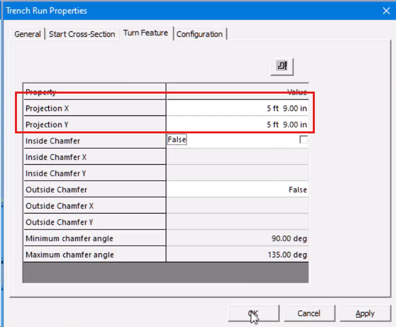
Select Finish to complete the path, and then select Properties. To define the turn features along the roadway, select the Turn Feature tab.
选择“完成”以完成路径,然后选择“属性”。要定义沿道路的转弯特征,请选择“转弯特征”选项卡。
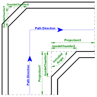
Enter values for Projection X and Projection Y to define the inside length of the turn feature along the x- and y-axis.
输入投影 X 和投影 Y 的值以定义转弯特征沿 x 轴和 y 轴的内部长度。
Select Finish again to complete the ditch placement. Here are the turn features.
再次选择“完成”以完成沟渠放置。以下是转弯特征。
Demonstration—Modify the Width of Features/Runs
演示 — 修改特征/运行的宽度
In this demonstration, we will show you how to change widths of trench features. You can increase trench widths to accommodate sections with greater flows to prevent excess spillage.
在此演示中,我们将向您展示如何更改沟槽特征的宽度。您可以增加沟槽宽度以适应流量更大的部分,以防止过度溢出。
As in the previous demonstrations, we are using the U12 workspace and coordinate system. Set the Locate Filter to Trench Features.
与之前的演示一样,我们使用 U12 工作区和坐标系。将定位过滤器设置为沟槽特征。
Select the trench feature section to change. Enter a new value to widen the trench feature section. Select Yes to overwrite the next feature and change the width of one side of the trench run.
选择要更改的沟槽特征部分。输入新值以加宽沟槽特征部分。选择“是”以覆盖下一个特征并更改沟槽运行一侧的宽度。
Now, let's change the width of another trench feature section. Enter the new width size. Select Yes again to overwrite the next feature.
现在,让我们更改另一个沟槽特征部分的宽度。输入新的宽度大小。再次选择“是”以覆盖下一个特征。
Smart 3D automatically updates any branch connections to accommodate changes in the width of the main run.
Smart 3D 会自动更新任何分支连接以适应主运行宽度的变化。
Demonstration—Add Chamfers to Trench Corners
演示 — 为沟槽角添加倒角
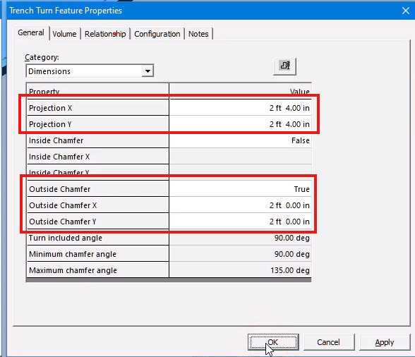
When adding the dimension properties for the chamfer, the trench corner Projection X & Y values must be greater than the outside chamfer values. Otherwise, Smart 3D displays an error. You can select Show Dimension Legend in the Properties dialog to review the properties that control the chamfer.
添加倒角的尺寸属性时,沟槽角投影 X 和 Y 值必须大于外部倒角值。否则,Smart 3D 会显示错误。您可以在“属性”对话框中选择“显示尺寸图例”来查看控制倒角的属性。
In this demonstration, you will see how to add a chamfer to a trench corner feature. Chamfers in a trench run can be added to increase the flow efficiency of a fluid or pipe run.
在此演示中,您将看到如何向沟槽拐角特征添加倒角。可以添加沟槽中的倒角以提高流体或管道的流动效率。
Set the Locate Filter to Trench Features. Select the corner feature to add the chamfer. Select Properties, and then choose Dimensions from the Category list.
将定位过滤器设置为沟槽特征。选择拐角特征以添加倒角。选择属性,然后从类别列表中选择尺寸。
Enter the Projection and Outside Projection X and Y values. Also set the Outside Chamfer to True. The outside chamfer now displays for the trench corner.
输入投影和外部投影 X 和 Y 值。还将外部倒角设置为 True。现在显示沟槽拐角的外部倒角。
Points to Remember
要点
Civil objects are placed in the model using information defined in the civil reference data. Your first step in your Civil design should be to review the delivered reference data using the Catalog task.
使用土木工程参考数据中定义的信息将土木工程对象放置在模型中。土木工程设计的第一步应该是使用目录任务查看交付的参考数据。
To place trenches, there are some considerations to review.
要放置沟槽,需要检查一些注意事项。
You can place a grid in which the intersections can be used to place a piping trench with a bottom slope that changes elevations.
您可以放置一个网格,其中的交叉点可用于放置底部坡度会改变高程的管道沟槽。
You can place straight trenches that do not have a slope in their configuration.
您可以放置配置中没有坡度的直沟槽。
After you have created your trench system, you can go back and modify trenches to accommodate varying flow intensities or piping space.
创建沟槽系统后,您可以返回并修改沟槽以适应不同的流量强度或管道空间。
You can add chamfers to a trench run to create curved corners for increased flow efficiency of a fluid or pipe run.
您可以在沟槽管路中添加倒角以创建弯曲的拐角,从而提高流体或管道管路的流动效率。
Place Cable Trenches
放置电缆沟
Overview
概述
Cable trenches are necessary in your plant design projects to accommodate underground electrical conduits. Smart 3D supports the creation of cable trenches with the same trench design workflow used for piping or drainage ditches. You will see how to create cable trenches and route an enclosed box trench.
电缆沟在您的工厂设计项目中必不可少,以容纳地下电气管道。Smart 3D 支持使用与管道或排水沟相同的沟渠设计工作流程来创建电缆沟。您将了解如何创建电缆沟和布置封闭的箱形沟。
Demonstration—Place Cable Trenches
演示—铺设电缆沟
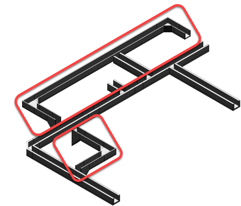

In this demonstration, we will place cable trenches beside a pipe trench run in the U12 workspace. We also have the Target to Origin PinPoint option selected.
在此演示中,我们将在 U12 工作区中的管道沟槽旁边放置电缆沟槽。我们还选择了“目标到原点”选项。
To get started, select Place Trench. Set the Cardinal Point, Placement Method, Top Slope, System, Type, and Cross-Section options to define the trench.
首先,选择“放置沟槽”。设置“基点”、“放置方法”、“顶部坡度”、“系统”、“类型”和“横截面”选项来定义沟槽。
Select Path to start sketching the cable trench path along the pipe trench. Enter East, North, and Elevation coordinate values.
选择“路径”开始沿管道沟槽绘制电缆沟槽路径。输入东、北和高程坐标值。
Select a point anywhere in the graphic view to place the first path point. Continue entering East and North values and selecting each path point in the view to place the trench. Use the North and East glyphs for alignment to draw each path point.
在图形视图中的任意位置选择一个点来放置第一个路径点。继续输入东和北值,并在视图中选择每个路径点来放置沟槽。使用北和东符号进行对齐以绘制每个路径点。
The last path point has a lower elevation to set up a connection underneath the pipe trench to the second cable trench.
最后一个路径点具有较低的高程,以在管道沟槽下方建立与第二个电缆沟槽的连接。
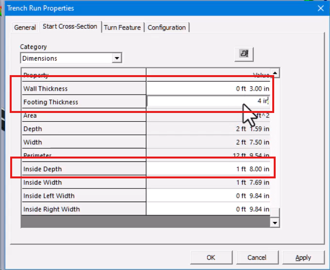
Select Finish to complete the path, and then select Properties. Select the Start Cross-Section tab, and then set the Footing Thickness, Wall Thickness, and Inside Depth properties.
选择“完成”以完成路径,然后选择“属性”。选择“开始横截面”选项卡,然后设置“基础厚度”、“壁厚”和“内部深度”属性。
Select Finish to place the first cable trench run. For the second cable trench run, select Place Trench again and keep the ribbon bar settings the same.
选择“完成”以放置第一个电缆沟槽。对于第二条电缆沟,再次选择“放置沟渠”,并保持功能区栏设置不变。
Select Path, and then enter the East and North coordinates. Enter the same Elevation coordinate as the previously placed point of the first cable trench.
选择“路径”,然后输入东和北坐标。输入与第一个电缆沟先前放置的点相同的高程坐标。
Select a point anywhere in the graphic view to start the path at the defined coordinates. Continue entering the coordinates for each path point. Remember to use the East and North glyphs for alignment.
在图形视图中的任意位置选择一个点,以在定义的坐标处开始路径。继续输入每个路径点的坐标。请记住使用东和北符号进行对齐。
For the last path point, define a lower elevation so that the cable trench can be connected and continued to run underneath the pipe trench.
对于最后一个路径点,定义一个较低的高程,以便电缆沟可以连接并继续在管道沟下方运行。
Select Finish to complete the path, and then select Properties. Select the Start Cross-Section tab, and then set the Footing Thickness, Wall Thickness, and Inside Depth properties.
选择“完成”以完成路径,然后选择“属性”。选择“开始横截面”选项卡,然后设置“基础厚度”、“壁厚”和“内部深度”属性。
Select Finish to place the second cable trench. Right-click to end the command.
选择“完成”以放置第二个电缆沟。右键单击以结束命令。
Demonstration—Place a Box Trench
演示—放置箱形沟槽

This demonstration builds on the previous demonstration in the U12 workspace. You will now see how to connect a cable trench that runs underneath a section of the piping trench using a box trench.
此演示基于 U12 工作区中的上一个演示。现在您将看到如何使用箱形沟槽连接位于管道沟槽下方的电缆沟槽。
Set the Locate Filter to Trench Runs, and then select the pipe trench next to the cable trench. Select Tools > Hide so that we can focus on the cable and box trenches.
将定位过滤器设置为沟槽运行,然后选择电缆沟槽旁边的管道沟槽。选择工具 > 隐藏,以便我们可以专注于电缆和箱形沟槽。
Let's zoom in closer on the area where the two cable trench pass under the pipe trench. Set the Locate Filter to All.
让我们放大两个电缆沟槽穿过管道沟槽下方的区域。将定位过滤器设置为全部。
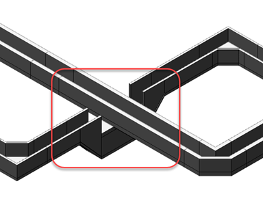
Select Place Trench, and then set the options in the Trench ribbon to define the box trench. Select Path, and then in the top gap, select the midpoint of the trench floor to start the box trench.
选择放置沟槽,然后设置沟槽功能区中的选项以定义箱形沟槽。选择路径,然后在顶部间隙中选择沟槽地板的中点以开始箱形沟槽。
Open the Common Views dialog and select the left, top corner glyph to rotate the view. Select the midpoint of the opposite trench floor to complete the box trench run.
打开常用视图对话框并选择左上角符号以旋转视图。选择对面沟槽地板的中点以完成箱形沟槽运行。
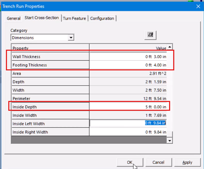
Select Finish to complete the path, and then select Properties. Select the Start Cross-Section tab, and then define the Footing Thickness, Wall Thickness, and Inside Depth properties.
选择完成以完成路径,然后选择属性。选择“起始横截面”选项卡,然后定义“基础厚度”、“壁厚”和“内部深度”属性。
Select Finish again to place the box trench. Right-click to end the command. To see all the trenches, select the hidden piping trench in the Workspace Explorer, and then select Tools > Show.
再次选择“完成”以放置箱形沟槽。右键单击以结束命令。要查看所有沟槽,请在工作区资源管理器中选择隐藏的管道沟槽,然后选择“工具”>“显示”。
Points to Remember
要点
Smart 3D supports the creation of cable and box trenches with the same trench design workflow used for piping or drainage ditches.
Smart 3D 支持使用与管道或排水沟相同的沟槽设计工作流程来创建电缆和箱形沟槽。
To place trenches, there are some considerations to review.
要放置沟槽,需要考虑一些事项。
You can create cable trench runs that can cross underneath existing pipe trench runs.
您可以创建可以穿过现有管道沟槽下方的电缆沟槽。
Use enclosed box trenches to connect cable trenches in areas underneath pipe trench runs.
使用封闭的箱形沟槽连接管道沟槽下方区域的电缆沟槽。
Modify Trenches
修改沟槽
Overview
概述
In this part, I will show you how to move a placed cable trench, insert a vertex transition feature to change the trench width, and then move the vertex.
在本部分中,我将向您展示如何移动已放置的电缆沟槽、插入顶点过渡特征以更改沟槽宽度,然后移动顶点。
Move a Cable Trench
Add a Vertex to Change a Cable Trench Width
Edit a Cable Trench Vertex
移动电缆沟槽
添加顶点以更改电缆沟槽宽度
编辑电缆沟槽顶点
Demonstration—Move a Cable Trench
演示 — 移动电缆沟
In this demonstration, we are moving the bottom cable trench in the north direction. We are using the U12 workspace and coordinate system.
在此演示中,我们将底部电缆沟向北移动。我们使用 U12 工作区和坐标系。
Let's set the Locate Filter to Trench Runs. Select the cable trench and select Fit to get a closer look.
让我们将“定位过滤器”设置为“沟渠运行”。选择电缆沟并选择“拟合”以更近距离查看。
Select Path, and then select the easterly path segment of the trench. The selected path highlights in red. Select the “From” Reference Point.
选择“路径”,然后选择沟渠的东向路径段。所选路径以红色突出显示。选择“从”参考点。
Position the cursor on the endpoint of the path, and press F6, F7, and F8 buttons to lock the current location values.
将光标定位在路径的端点上,然后按 F6、F7 和 F8 按钮锁定当前位置值。
Select any point in the graphic view to enter the current location as the “from” reference for the move.
选择图形视图中的任意点以输入当前位置作为移动的“从”参考。
Position the cursor again on the path endpoint, and then press F6 and F8 to lock the East and Elevation values.
再次将光标定位在路径端点上,然后按 F6 和 F8 锁定“东”和“高程”值。
Enter 4 ft. 6 in. in the North field. Select a point in the graphic view, and then select Finish.
在“北”字段中输入 4 英尺 6 英寸。在图形视图中选择一个点,然后选择“完成”。
Select Yes to overwrite the trench run. The cable trench displays in the new position.
选择“是”以覆盖沟渠运行。电缆沟显示在新位置。
Demonstration—Add Vertex Transition Features to a Cable Trench
演示 — 向电缆沟添加顶点过渡特征
This demonstration shows how to change the width of a trench by adding vertex transition features. To get started, set the Locate Filter to Trench Runs, and then select the cable trench to edit.
此演示展示了如何通过添加顶点过渡特征来更改沟渠的宽度。首先,将“定位过滤器”设置为“沟渠运行”,然后选择要编辑的电缆沟渠。
Select Path, and then select the easterly path segment of the trench. The path displays in red. Select Insert Vertex, and then enter 53 ft. 5 in. in the East field.
选择“路径”,然后选择沟渠的东向路径段。路径显示为红色。选择“插入顶点”,然后在“东”字段中输入 53 英尺 5 英寸。
Position the cursor on the path line and left click anywhere on the line for the first vertex. Now enter 52 ft. 2.5 in. in the East field.
将光标定位在路径线上,然后在该线上的任意位置单击鼠标左键以输入第一个顶点。现在在“东”字段中输入 52 英尺 2.5 英寸。
Position the cursor on the path line, and then left click for the second vertex. Select Finish to complete the path change, and then select Finish again to add the feature.
将光标定位在路径线上,然后左键单击以输入第二个顶点。选择“完成”以完成路径更改,然后再次选择“完成”以添加特征。
Select OK to overwrite the existing run. Now set the Locate Filter to Trench Features. Select the new feature, and then set the Start Inside Left Width to 8 in.
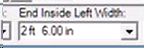
选择“确定”以覆盖现有运行。现在将“定位过滤器”设置为“沟渠特征”。选择新特征,然后将“起始内部左侧宽度”设置为 8 英寸。
Select Yes to Overwrite. Set the Start Inside Right Width to 8 in., and then select Yes to Overwrite. The new width for the trench segment displays.
选择“是”以覆盖。将“起始内右宽度”设置为 8 英寸,然后选择“是”以覆盖。将显示沟槽段的新宽度。
Demonstration—Move a Cable Trench Vertex
演示 — 移动电缆沟顶点
This demonstration shows how to modify a cable trench by moving its vertex. Set the Locate Filter to Trench Runs, and then select the pipe trench that runs above the cable trench.
此演示展示了如何通过移动电缆沟的顶点来修改电缆沟。将“定位过滤器”设置为“沟渠运行”,然后选择运行在电缆沟上方的管道沟渠。
Select Tools > Hide. Select the cable trench to edit, and then select Fit to zoom in. Select Path, and then select the vertex point at the end of the trench path.
选择“工具”>“隐藏”。选择要编辑的电缆沟渠,然后选择“适合”以放大。选择“路径”,然后选择沟渠路径末端的顶点。
Select the "From" Reference Point, and then select the vertex point again. Alternatively, press F6, F7, and F8 to lock the current location values, and then left click anywhere in the graphic view.
选择“从”参考点,然后再次选择顶点。或者,按 F6、F7 和 F8 锁定当前位置值,然后在图形视图中的任意位置单击鼠标左键。
The command automatically activates the “To” End Point button. Move the cursor down the path, and then select the new vertex location.
该命令会自动激活“到”终点按钮。将光标沿路径向下移动,然后选择新的顶点位置。
Or continue using the function keys to lock the North and Elevation values. You can enter an East value, and then left click anywhere in the graphic view.
或者继续使用功能键锁定“北”和“高程”值。您可以输入“东”值,然后在图形视图中的任意位置单击鼠标左键。
Select Finish to complete the path modification. Select Finish again to update the trench geometry. Select Yes to overwrite the trench run.
选择“完成”以完成路径修改。再次选择“完成”以更新沟渠几何形状。选择“是”以覆盖沟渠运行。
The updated trench run displays.
显示更新后的战壕运行。
Key Points and Tips
要点和提示
The Civil task provides tools you can use to move, edit, or remove previously placed trench objects.
Civil 任务提供了可用于移动、编辑或移除先前放置的沟槽对象的工具。
Add vertex transition features to change the width of segments or the entire trench path.
添加顶点过渡特征以更改段的宽度或整个沟槽路径。
You can modify a trench by moving its vertices.
您可以通过移动沟槽的顶点来修改沟槽。
A cable tray system can be added to the workspace to review a cable tray and a trench together.
可以将电缆托盘系统添加到工作区,以便同时查看电缆托盘和沟槽。
Covering Trenches
覆盖沟渠
Overview
概述
Trenches can be covered by either concrete slabs or some type of grating. The video demonstrations in this course show how to add such coverings to a trench. A covering might be shaped to conceal a straight trench or they could be polygonal in dimension to accommodate a trench run which has differing widths.
沟渠可以用混凝土板或某种类型的格栅覆盖。本课程中的视频演示展示了如何将此类覆盖物添加到沟渠中。覆盖物可以制成形状以隐藏直沟渠,也可以是多边形尺寸以适应具有不同宽度的沟渠。
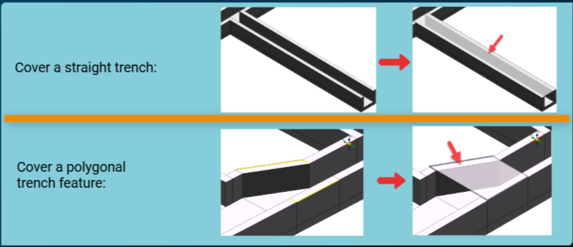
Demonstration—Cover a Straight Trench Run
演示 — 覆盖直沟槽

In this demonstration, we are using the U12 workspace to place a slab on a straight trench run. For our example, we are working with a trench run that is already in place.
在此演示中,我们使用 U12 工作区在直沟槽上放置板。在我们的示例中,我们使用已就位的沟槽。
You can use the Tools > Hide command to filter your display and focus on the straight trench run to cover.
您可以使用“工具”>“隐藏”命令过滤显示并聚焦要覆盖的直沟槽。
Select the straight trench, and then select Fit to zoom in. Right-click or press Escape to end the selection, and then set the Locate Filter to All.
选择直沟槽,然后选择“适合”以放大。右键单击或按 Esc 键结束选择,然后将“定位过滤器”设置为“全部”。
Now let's select the Place Slab command. Set the System to A1 > U12 > Civil_Structure > Slabs, and then set the Type of cover to use.
现在让我们选择“放置板”命令。将“系统”设置为 A1 > U12 > Civil_Structure > 板”,然后设置要使用的覆盖类型。
Select the top surface of the trench wall for the support plane, and then select Accept. For the cover boundary, select the four edge lines of the trench walls. The Quick Pick feature helps you select the lines.
选择沟槽壁的顶面作为支撑平面,然后选择“接受”。对于覆盖边界,选择沟槽壁的四条边缘线。快速拾取功能可帮助您选择线条。
Select Finish to place the cover. Right-click or press ESC to end the Place Slab command. To change the trench and cover width, set the Locate Filter to Trench Runs, and then select the trench.
选择“完成”以放置覆盖。右键单击或按 ESC 键结束“放置板”命令。要更改沟槽和覆盖宽度,请将“定位过滤器”设置为“沟槽运行”,然后选择沟槽。
Select Properties, and then select the Start Cross-Section tab. Set the Inside Left Width to 1 ft. Select Yes to overwrite the feature properties.
选择“属性”,然后选择“开始横截面”选项卡。将“内部左侧宽度”设置为 1 英尺。选择“是”以覆盖要素属性。
The cover updates with the width change applied to the trench run.
覆盖会根据沟槽运行的宽度变化进行更新。
Demonstration—Cover a Trench Feature
演示 — 覆盖沟槽特征

This demonstration shows how to place a slab cover over a trench section with varying widths. Again, you are working in the U12 workspace with a series of trenches already in place.
此演示展示了如何在具有不同宽度的沟槽部分上放置板盖。同样,您正在 U12 工作区中工作,其中已经存在一系列沟槽。
Set the Locate Filter to Trench Features, and then select a transition feature in the trench run. Select Place Slab, and then set the System to Slabs.
将“定位过滤器”设置为“沟槽特征”,然后选择沟槽运行中的过渡特征。选择“放置板”,然后将“系统”设置为“板”。
Set the Type to a slab grating to use. Select the top surface of the trench wall for the support plane, and then select Accept.
将“类型”设置为要使用的板格栅。选择沟槽壁的顶面作为支撑平面,然后选择“接受”。
Select the four edge lines of the trench walls to define the slab boundary. The Quick Pick can help you select each line.
选择沟槽壁的四条边线以定义板边界。“快速拾取”可以帮助您选择每条线。
Select Finish to place the grating on the transition feature. The slab now covers the polygonal transition feature in the trench run.
选择“完成”以将格栅放置在过渡特征上。板现在覆盖了沟槽运行中的多边形过渡特征。
Key Points and Tips
要点和提示
Trenches can be covered by either concrete slabs or some type of grating.
沟槽可以用混凝土板或某种类型的格栅覆盖。
Use the Cross-Section properties to change trench run and slab cover widths.
使用“横截面”属性来更改沟槽运行和板盖宽度。
Use the Place Slab command to add a trench cover.
使用“放置板”命令添加沟槽盖板。
You can modify a trench by moving its vertices.
您可以通过移动沟槽的顶点来修改沟槽。
Select all four edge lines of trench walls to define the bounchary for the slab cover.
选择沟槽壁的所有四条边线来定义板盖板的边界。
Closeout Walls & Openings
收尾墙和开口
Overview
概述
In Smart 3D, you can insert a closeout wall by using a traditional wall placed at the end point of a trench or its branches. Openings on a trench run can be inserted when a piping layout becomes situated with an overlap. Click each Info button below for additional details.
在 Smart 3D 中,您可以使用放置在沟槽或其分支端点的传统墙来插入收尾墙。当管道布局重叠时,可以插入沟槽上的开口。单击下面的每个信息按钮以获取更多详细信息。
- Use the standard Place Wall command for the closeout wall in a trench run.
-
To draw a closeout wall, you are placed in the Sketch 3D environment.
-
使用标准的 放置墙 命令绘制沟槽中的收尾墙。
- 要绘制收尾墙,您需要进入 Sketch 3D 环境。
When you are cutting an opening in a trench wall or part within a trench run, the software places you in the Sketch 2D environment.
当您在沟槽墙或沟槽内切割开口时,软件会将您置于 Sketch 2D 环境中。
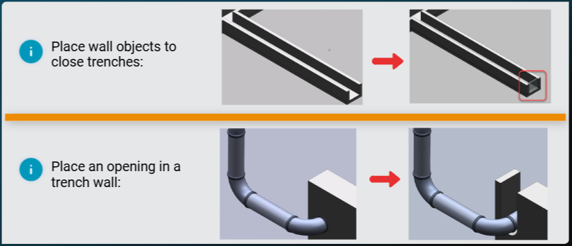
Demonstration—Place a Closeout Wall on a Trench Run
演示 — 在沟槽上放置收尾墙

This video shows how to place a closeout wall on an existing trench run in the U12 workspace. Let's start by setting the Locate Filter to Trench Runs, and then zooming in to the end of a trench.
此视频展示了如何在 U12 工作区中在现有沟槽上放置收尾墙。首先,将“定位过滤器”设置为“沟槽”,然后放大到沟槽末端。
Turn off the PinPoint command, and then select Place Wall. Set the System to Walls, and then define wall properties to fit the trench end.
关闭“PinPoint”命令,然后选择“放置墙”。将“系统”设置为“墙”,然后定义墙属性以适合沟槽末端。
Select the bottom surface of the trench as the sketching plane, and then select 3D to sketch the wall path.
选择沟槽的底面作为草图平面,然后选择 3D 绘制墙路径。
Select the geometry key point of the inside trench wall to start the path. Now select the geometry key point of the inside trench wall on the other side to end the path.
选择沟槽内壁的几何关键点以开始路径。现在选择另一侧沟槽内壁的几何关键点以结束路径。
Select Finish to complete the path and exit the 3D sketcher. Select Finish again to place the closeout wall.
选择“完成”以完成路径并退出 3D 草图绘制器。再次选择“完成”以放置收尾墙。
Demonstration—Place an Opening on a Trench Run
演示 — 在沟槽上放置开口
In this demonstration, we will show you how to cut an opening through a trench run. This opening allows you to see and access a conflicting pipe run going through the trench.
在此演示中,我们将向您展示如何在沟槽上切割开口。此开口允许您查看和访问穿过沟槽的冲突管道。
We are using the U12 workspace modified to include the Pipelines and the Pipe Trenches system folders. To get started, let's zoom in to the area where the pipe penetrates the trench wall.
我们使用经过修改的 U12 工作区,其中包括管道和管道沟槽系统文件夹。首先,让我们放大管道穿透沟槽壁的区域。
Select the Place Opening command, and then select the trench wall. Select the wall surface, and then select Add references to sketch 2D.
选择“放置开口”命令,然后选择沟槽壁。选择壁面,然后选择“添加参考以绘制 2D 草图”。
Select the penetrating pipe section, and then select Draw to enter the 2D Sketcher. Select Tools > Layers, and then select Layer Display.
选择穿透管道部分,然后选择“绘制”以进入 2D 草图绘制器。选择“工具”>“图层”,然后选择“图层显示”。
Select No Constrained Elements to turn this layer off. Select Circle by Center Point, and then enter 5 in. for the Diameter.
选择“无约束元素”以关闭此图层。选择“按中心点画圆”,然后输入 5 英寸作为直径。
Select the center point of the pipe to place the circle concentric to the pipe. Select the green Accept check to save and close Sketch 2D. You can now see the pipe opening.
选择管道的中心点以放置与管道同心的圆。选择绿色的“接受”复选标记以保存并关闭 2D 草图。现在您可以看到管道开口。
Select Place Opening again, and then select the trench wall. Select the wall surface, and then select Add references to sketch 2D.
再次选择“放置开口”,然后选择沟槽壁。选择壁面,然后选择“添加参考到草图 2D”。
Select the penetrating pipe section, and then select Draw. Select Circle by Center Point, and then enter 5 in. for the Diameter.
选择穿透管道部分,然后选择“绘制”。选择“按中心点画圆”,然后输入 5 英寸作为直径。
Select the center point of the pipe to place the circle concentric to the pipe. Select Place Line, and then select the left side of the circle with the horizontal dashed line showing and the Point on constraint.
选择管道的中心点以放置与管道同心的圆。选择“放置线”,然后选择显示水平虚线的圆的左侧和“点在约束上”。
Draw the line upward until it clears the top of the trench wall, and then left click to place the line.
向上绘制线,直到它越过沟槽壁的顶部,然后单击左键以放置线。
Right click to start a new line, and then click the right side of the circle with the horizontal dashed line.
右键单击以开始一条新线,然后单击带有水平虚线的圆的右侧。
Draw the line upward until it is even with the top of the previous line, and then left click to place the second line.
向上绘制线,直到它与上一条线的顶部齐平,然后单击左键以放置第二条线。
Draw a horizontal line between the ends of the two vertical lines. Select Trim, and then select the top half of the circle to remove it.
在两条垂直线的末端之间绘制一条水平线。选择“修剪”,然后选择圆的上半部分以将其移除。
Select Accept to save and close Sketch 2D, and then select Finish. The open slot displays on the trench.
选择“接受”以保存并关闭草图 2D,然后选择“完成”。沟槽上将显示开口槽。
Key Points and Tips
要点和提示
The trench run flow can be blocked by placing a traditional wall at the end point of a trench or its branches.
通过在沟槽或其分支的端点放置传统墙壁,可以阻止沟槽流动。
Cutting an opening in a trench run allows your piping layout to be routed without conflict.
在沟槽中切割开口可让您的管道布局无冲突地进行。
When placing a wall, the software enters you into the Sketch 3D environment.
放置墙壁时,软件会将您带入 Sketch 3D 环境。
To cut out an opening or a slot, the software enters you into the Sketch 2D drawing environment.
要切割开口或槽口,软件会将您带入 Sketch 2D 绘图环境。