
Demo Project
约 4087 个字 预计阅读时间 14 分钟
The following article details the process of setting up the asset bundle and scenario shipped as part of the demo projects of 3D PACT.
Resources:
Below you can download the completed source facility, asset bundle and scenario.
| Resource | Download |
|---|---|
| Combined Cycle Unity Package | .unitypackage |
| Combined Cycle Asset Bundle | .bundle |
| “Extinguish Fire & Evacuate“ Scenario | .scenario |
The following links outline how to upload them to the 3D PACT Management Systems (MS) and import them into the 3D PACT Instructor Station and execute the scenario in the 3D PACT Trainee Station
Scenario Objective
In the Combined Cycle Facility, spawn the participant in as well as 3 Non Player Characters (NPCs). The NPCs should be made to walk to designated locations of your choice. Create Tasks in which the participant needs to identify the value and open it. A fire particle system is then triggered. The user should then be tasked with identifying the fire, retrieving and activating the fire extinguisher, extinguishing the fire. Once extinguished, the participant and all 3 NPCs should move to the designated evacuation point, after which the scenario is concluded.
The Approach
Step 1: Configuring the Facility
Step 1.1: Create a New Unity Project
-
Launch Unity Hub
-
Click “New project“
-
Ensure you select the Unity Editor Version
2022.2.24f1 -
Give your Project a name, like “Combined Cycle“
-
Optional: Link your project to a Version Control System (VCS), like Plastic, GitHub etc.
-
Click “Create project“
Step 1.2: Install the 3D PACT Engineer Station (ES) Package
-
In the Unity Project, click
Assets→Import→Custom Package... -
Find your local copy of the 3D PACT Engineer Station (ES) Package and click
Open- If you don't have one, download it here:
-
Allow some time for the import to complete
-
Once complete, in the toolbar, you will see an
Engineermenu option
Step 1.3: Import the Combined Cycle package
-
In the Unity Project, click
Assets→Import→Custom Package... -
Find your local copy of the Combined Cycle Unity Package and click
Open- If you don't have one, download it here:
-
Allow some time for the import to complete
-
Once complete, you should see the Combined Cycle Scene
Step 1.4: Configure the Valve and Fire Particle System
For more information on how to set up Interactables, seeCreating Interactables.
Configure the Valve
-
Locate the Valve model in the Hierarchy
-
Add to the Valve
Game Object:-
An
Interactable Visualcomponent -
A
Collider
-
-
Navigate, in the Project folder, to
Assets→ClientFiles→Prefabs→Interaction Statesand drag theRotate Stateprefab into the Hierarchy

-
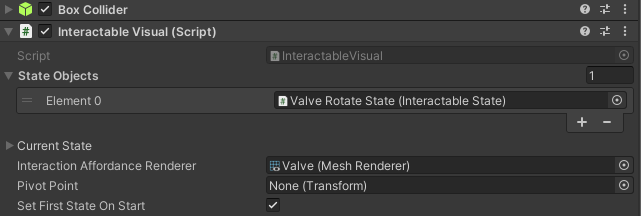
On the
Interactable Visualcomponent of the Valve:-
Drag the
Rotate Stateprefab into theState Objectsarray -
Optionally drag the Valve’s
Mesh Rendererinto theInteraction Affordance Renderervariable
-
-
Next, we will set up the Valve to switch between opened and closed states, so that scenarios can check if a
Traineehas performed either action. See Visual Scripting Interactable Logic for more detail onVisual Scripting -
Add a
State Machinecomponent to the Valve -
Click the '
New' button:-
Name the
State Graph‘Valve’ -
Save the
State Graphto the ‘Graphs’ folder
-
-
Click the '
Edit Graph' button -
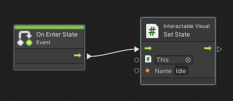
Double-click on the ‘Start’ node and remove everything except for the ‘On Enter State’ node
-
Right-click and search for ‘Interactable Visual Set State’ and choose the first option to set the state name to ‘Idle’
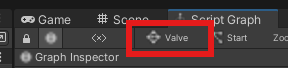
- Navigate out of the ‘Start’ node by clicking on the ‘Valve’
State Graphtab on the top left
-
Right-click and select ‘
Create Script State' and rename it to 'Opened’ in theGraph Inspectoron the left -
Double-click on the
Script Stateand again remove all nodes except for theOn Enter Statenode -
Right-click and search for ‘Interactable Visual Set State’ and choose the first option to set the state name, this time to ‘Opened’
-
Copy your ‘Opened’
Script Statenode (right-click copy and paste) -
Rename the new
Script Stateto ‘Closed’ in theGraph Inspectorand, inside theScript State, rename the state name to ‘Closed’ -
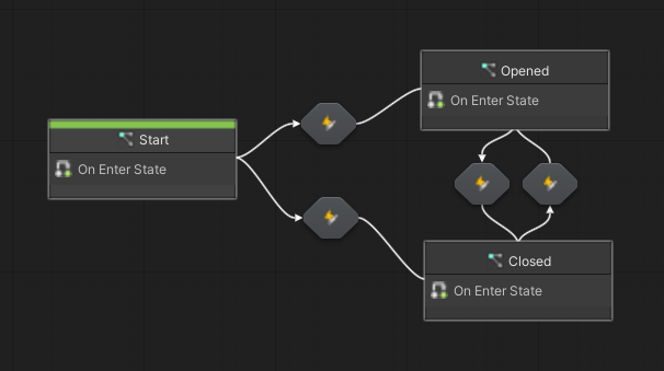
Now that all states are set up, it’s time to create the
Transitionsbetween them -
Right-click on the ‘Start’ node, select ‘
Make Transition’, and click on the ‘Opened’ node -
Repeat this step to make
Transitionsfrom ‘Start’ to ‘Closed’, from ‘Opened’ to ‘Closed’, and from ‘Closed’ to ‘Opened’
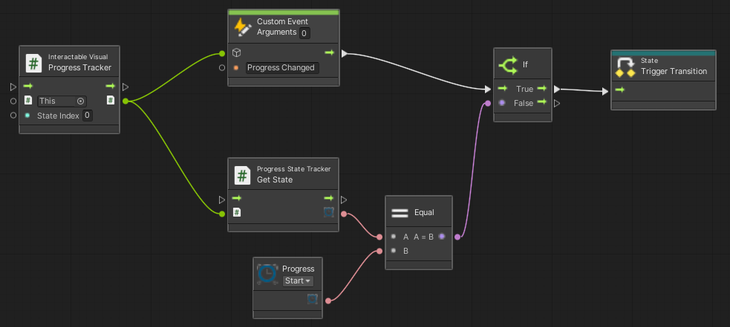
- Double-click on the Transition from ‘Start’ to ‘Opened’ to edit it
- Trigger the
Transitionwhen the rotation progress has reached ‘Start’ (the minimum rotation limit) using aCustom Event‘Progress Changed’. For more information on progress tracking and the Rotate State, see Interactable States.
-
Copy and paste these nodes inside all
Transitions -
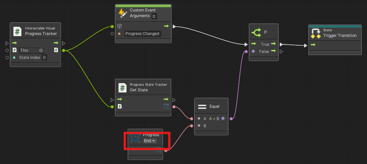
In the
Transitionspointing to ‘Closed’ ('Start' → ‘Closed’ and ‘Opened’ → ‘Closed'), changed the ‘Progress’ variable to ‘End’ to check when the progress has reached ‘End’ (the maximum rotation limit)
- The Valve will now change its state name to ‘Opened’ when it is turned all the way to the left and ‘Closed’ when it is turned all the way to the right - this means that the
Scenario Editorcan check when the Valve has been opened or closed
Configure the Fire Particle System
-
Navigate in the Project folder to
Assets→_Project→Prefabs→Firesand drag and drop the desired fire particles prefab into the scene -
Create an empty
Game Objectand name it ‘Fire’ -
Move the fire particles prefab into the ‘Fire’
Game Objectand reset itsTransform -
To the ‘Fire’
Game Object, add anInteractable Visualcomponent and aCollider -
Resize the
Colliderto encapsulate the fire particles
Step 1.5: Configure the Gaze Interaction for the Fire Particle System
Configure the Fire Particle System Logic
-
Navigate, in the Project folder, to
Assets→ClientFiles→Prefabs→Interactable States -
Drag the
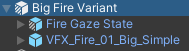
Gaze Stateprefab into the Hierarchy and rename it to ‘Fire Gaze State’
-
Drag the ‘Fire Gaze State’
Game Objectinto theState Objectsarray on theInteractable Visualcomponent of the 'Fire'Game Object -
Add a
State Machinecomponent to the ‘Fire’Game Object -
Click the '
New' button:-
Name the
State Graph‘Fire’ -
Save the
State Graphto the ‘Graphs’ folder
-
-
Click the '
Edit Graph' button -
The goal of the Fire logic is to:
-
Spawn the Fire particles when the Valve is opened
-
Set its state name to ‘Located’ when the user looks at the Fire - this is the purpose of the
Gaze State -
Decrease the Fire’s health and number of particles while the Extinguisher is being used
-
Set the Fire’s state name to ‘Put Out’ when its health reaches 0
-
Hide the Fire and reset its health and particles (in case it needs to spawn again)
-
-
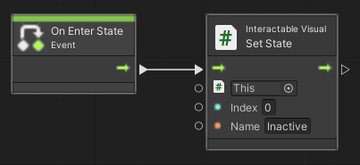
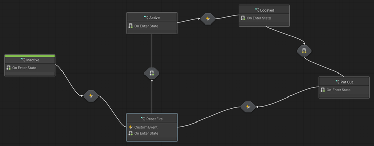
Double-click on the ‘Start’ node, rename it to ‘Inactive’, and remove everything except for the ‘On Enter State’ node
-
Right-click and search for ‘Interactable Visual Set State’ and choose the first option to set the state name to ‘Inactive’ - the Fire has not yet spawned
-
Navigate out of the ‘Inactive’ node by clicking on the ‘Fire’
State Graphtab on the top left -
Right-click and select ‘
Create Script State' and rename it to 'Active’ in theGraph Inspector(on the left) -
Repeat this last step to create
Script Statesfor ‘Reset Fire’, ‘Located’, and ‘Put Out’ -
Make
Transitionsfrom ‘Start’ → ‘Reset Fire’, ‘Reset Fire’ → ‘Active’, ‘Active' → ‘Located’, ‘Located’ → ‘Put Out’, and ‘Put Out’ back to 'Reset Fire’
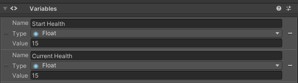
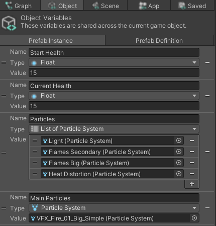
- On the
Variablescomponent of the FireGame Object, create two floatObject Variables‘Start Health’ and ‘Current Health’
-
Inside the ‘Reset Fire’ node, we need to reset the maximum particles for each
Particle Systemof the Fire- Create a list of
Particle SystemObject Variablecalled ‘Particles’ and drag in all of the FireParticle Systems
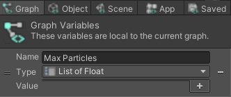
- Create a list of
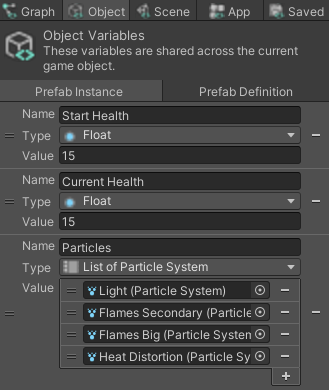
- Create a list of float
Graph Variablecalled ‘Max Particles’
- Now, initialize the ‘Max Particles’
Graph Variableto the actual max particles of eachParticle Systemin the ‘Particles’Object Variableby creating aCustom Eventnode called ‘Set Max Particles’
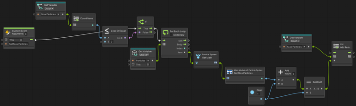
-
Next, create another
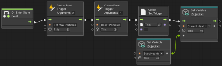
Custom Event‘Reset Particles’ to reset the max particles of eachParticle Systemin the ‘Particles’Object Variableto the floats in the ‘Max Particles’Graph Variable. This event can now be called whenever the Fire’s particles need to be reset after being extinguished- Finally ‘On Enter State’, trigger the
Custom Events, setisTriggeron theColliderto false so that the fire can be selected withGaze State, and initialize ‘Current Health’ to ‘Start Health’
- Finally ‘On Enter State’, trigger the
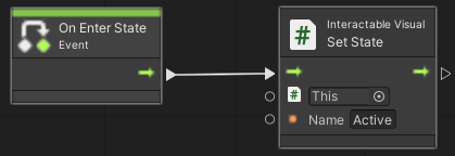
- Inside the ‘Active’ node, simply set the state name to ‘Active’
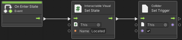
- Inside the ‘Located’ node, set the state name to ‘Located’ and set
isTriggeron theColliderto true so that theCollidercan no longer be selected withGaze State
- Inside the ‘Put Out’ node, set the state name to ‘Put Out’
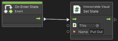
-
Now we need to set up the
Transitionsbetween the states -
Create another
Object Variable‘Main Particles’ and drag in the parentParticle System
- ‘Inactive’ → ‘Reset Fire’: the Fire particles should reset each time the Fire is spawned, so we will create a ‘Spawn Fire’
Custom EventtoTransitionfrom ‘Inactive’ to ‘Reset Fire’. The Valve can then call this event when opened, and that will trigger the transition to reset the Fire
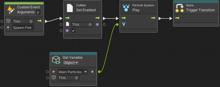
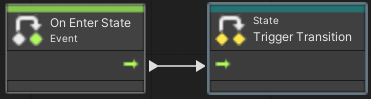
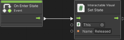
- ‘Reset Fire' → ‘Active’: nothing needs to happen, so the
Transitioncan automatically trigger
Open Screenshot 2024-07-25 115304.png
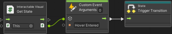
- ‘Active’ → ‘Located’: wait for the ‘Hover Entered' event on the
Gaze Stateto check if the user has looked at the Fire
-
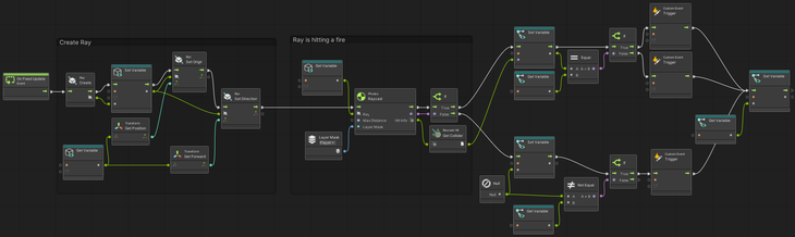
‘Located’ → ‘Put Out’: reduce the Fire health and particles when it is being extinguished
- First, we need to define emission constants for each
Particle System- at what rate should eachParticle Systemreduce its particle count, such that all particles are diminish at the same time? Create a list of floatGraph Variable‘Emission Constants’
- First, we need to define emission constants for each
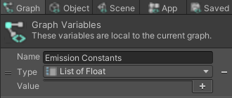
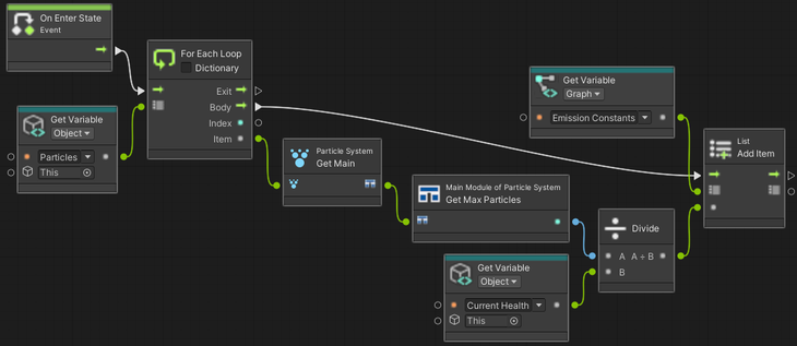
- Set the each item in ‘Emission Constants’
Graph Variableto the max particles of each ‘Particles’Object Variabledivided by ‘Current Health’
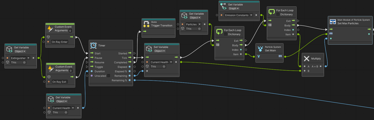
- Wait for the ‘On Ray Entered’
Custom Eventto be called from the Extinguisher (when the Extinguisher is pointing at the Fire), and reduce the Fire’s health and the number of particles of each FireParticle Systemin the ‘Particles’Object Variable
- ‘Put Out’ → ‘Reset Fire’: copy ‘Spawn Fire’
Custom Eventnodes from the ‘Inactive’ → ‘Reset Fire’Transitionto reset the Fire after it's been put out whenever the ‘Spawn Fire’ event is called
Step 1.6: Configure the Fire Extinguisher and interaction with Fire Particle System
Configure the Fire Extinguisher
-
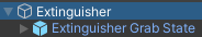
Search the Project folder for the extinguisher model and drag and drop it into the Hierarchy
-
Rename the model to ‘Extinguisher’
-
To the ‘Extinguisher’
Game Object, add anInteractable Visualcomponent and aCollider -
Navigate, in the Project folder, to
Assets→ClientFiles→Prefabs→Interactable States -
Drag the
Grab Stateprefab into the Hierarchy and rename it to ‘Extinguisher Grab State’
-
Drag the ‘Extinguisher Grab State’
Game Objectinto theState Objectsarray of theInteractable Visualcomponent -
The Extinguisher is now grabbable
Configure the Fire Extinguisher Logic
-
Add a
State Machinecomponent to the Extinguisher -
Click the '
New' button:-
Name the
State Graph‘Extinguisher’ -
Save the
State Graphto the ‘Graphs’ folder
-
-
Click the '
Edit Graph' button -
The goal of the Extinguisher logic is to:
-
Set the state name when it is grabbed and released
-
When the trigger key is pressed, play Extinguisher particles and shoot a ray to detect if the particles are hitting a
Collider(the Fire) -
Stop the particles and reset the ray when the trigger key is released
-
Create
Custom Events‘On Ray Enter’ and ‘On Ray Exit’ to call in the Fire logic
-
-
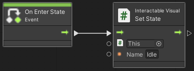
Double-click on the ‘Start’ node and remove everything except for the ‘On Enter State’ node
-
Right-click and search for ‘Interactable Visual Set State’ and choose the first option to set the state name to ‘Idle’
-
Navigate out of the ‘Start’ node
-
Right-click to ‘
Create Script State' and rename it to 'Grabbed’ in theGraph Inspector(on the left) -
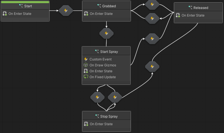
Copy the ‘Grabbed’ script state 3 times and rename each to ‘Released’, ‘Start Spray’, and ‘Stop Spray’
-
Next, make
Transitionsbetween ‘Start’ → ‘Grabbed’, ‘Grabbed’ → ‘Released’, ‘Released’ → ‘Grabbed’, ‘Grabbed’ → ‘Start Spray’, ‘Start Spray’ → ‘Stop Spray’, ‘Stop Spray’ → ‘Start Spray’, ‘Start Spray’ → ‘Released’, and ‘Stop Spray’ → ‘Released’
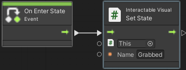
- Inside the ‘Grabbed’ node, set the state name to ‘Grabbed’
- Inside the ‘Released’ node, set the state name to ‘Released’
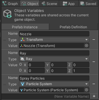
- For the spraying logic, we will need to create some
Object Variables: ‘Ray’ (to detect if the spray is hitting the fire), ‘Spray Particles' (the sprayParticle System), and the ‘Nozzle’ (where the ‘Ray’ and particles should shoot from)
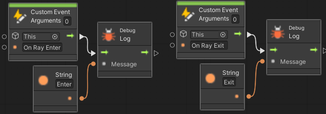
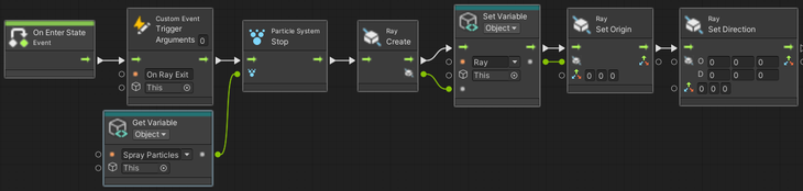
- Inside the ‘Start Spray’ node, first create the ‘On Ray Enter’ and ‘On Ray Exit’
Custom Events
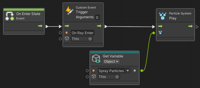
- Next, ‘On Enter State’, trigger the ‘On Ray Enter’
Custom Eventand play the ‘Spray Particles’
-
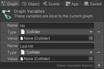
Now we need to set the Ray’s position to the ‘Nozzle’ in a forward direction, and check if it hits anything
- First, create two
CollidertypeGraph Variables‘Hit’ and ‘Last Hit' to check each frame if the Ray has entered a newCollider
- First, create two
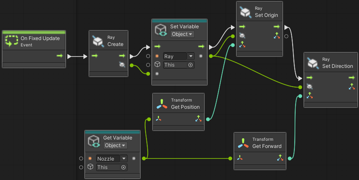
- Create the Ray and, every frame ('On Fixed Update'), set its position to the Nozzle position and its direction to the direction in which the Nozzle is pointing (forward)
- Check if the Ray has hit a
Collider
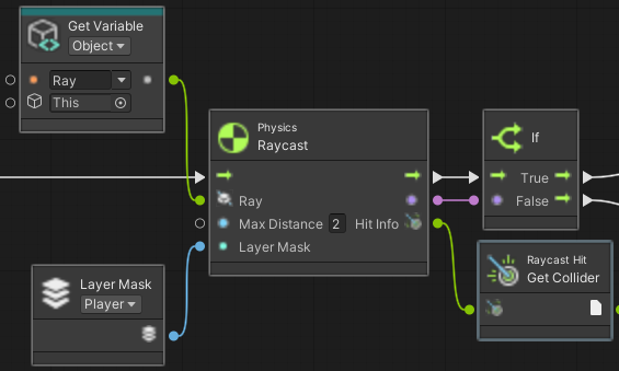
- If it has hit a
Collider, if theColliderthat was hit ('Hit') is not the same as theColliderthat was previously hit ('Last Hit'), trigger the ‘On Ray Enter’Custom Eventarguments and finally set ‘Last Hit’ to ‘Hit’
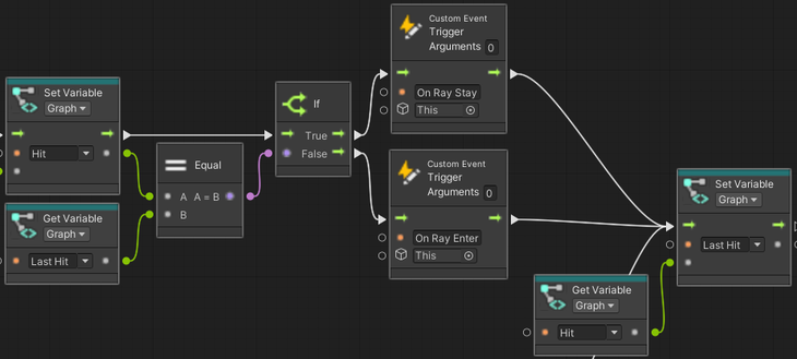
- Otherwise, if no
Colliderwas hit, set ‘Hit' to null. If theColliderthat was previously hit (‘Last Hit’) exists, trigger the ‘On Ray Exit’Custom Eventarguments and finally set ‘Last Hit’ to ‘Hit’
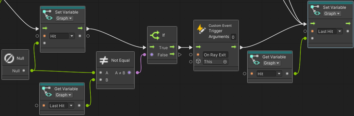
- The full graph to shoot the Ray and detect collisions connects as follows:
- Inside the ‘Stop Spray’ node, trigger the ‘On Ray Exit’
Custom Eventarguments, reset the position and direction of the Ray, and stop playing the Spray ParticlesParticle System
-
Now we need to set up the
Transitions:-
For the
Transitionsto ‘Grabbed’ (from ‘Start’ → ‘Grabbed’ and ‘Released’ → ‘Grabbed’), wait for the ‘Select Entered’Custom Event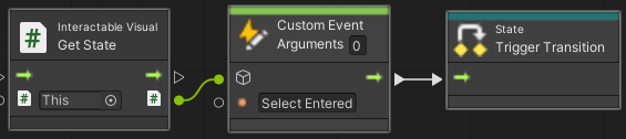
-
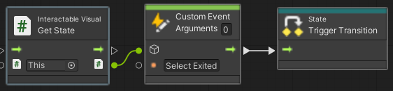
For the
Transitionsto ‘Released’ (from ‘Grabbed’ → ‘Released’, ‘Start Spray’ → ‘Released’, and ‘Stop Spray’ → ‘Released’), wait for the ‘Select Exited’Custom Event
-
For the
Transitionsto ‘Start Spray’ (from ‘Grabbed’ → ‘Start Spray’, and ‘Stop Spray’ → ‘Start Spray’), wait for the ‘Activated’Custom Event, which checks when the trigger key is pressed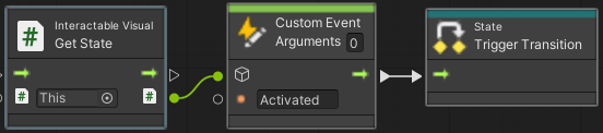
-
For the
Transitionto ‘Stop Spray’ (from ‘Start Spray’ → ‘Stop Spray’), wait for the ‘Deactivated’Custom Event, which checks when the trigger key is released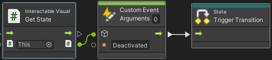
-
Step 1.7: Test the Environment Logic
-
Search the Project folder for ‘XR Interaction Hands Setup’
-
Drag and drop the ‘XR Interaction Hands Setup’ into the scene and position it near your
Interactables -
Enable Quest Link in your headset
-
Click the Unity ‘Play’ button
-
You will now be able to interact with your
Interactablesin VR -
Make sure you remove the ‘XR Interaction Hands Setup’ prefab from your scene before exporting
Step 1.8: Login and Export the Asset Bundle to the 3D PACT Management System
-
In the Unity Project, in the tool bar click
Engineer→Import/Export -
In the window, enter your 3D PACT Management System Tenant Name, Username and Password
-
NOTE: This user account should have the minimum permissions of an Engineer User
-
Don’t know these details? Read more here: [User Guide - 3D PACT Management System (MS)]
-
-
In the window, click
Export→New -
Select an appropriate Company & Facility
- Don’t know what these are? Read more here: [User Guide - 3D PACT Management System (MS)]
-
Give the Asset Bundle a name, description and select the
Lockedoption- What's the difference? Read more here: [User Guide - 3D PACT Management System (MS)]
-
Allow some time for the Export to take place. Keep track of progress through the Editor Console
- What is going on behind the scenes? Read more here: [User Guide - 3D PACT Engineer Station (ES)]
Step 2: Creating & Testing the Scenario
Step 2.1: Login into 3D PACT Instructor Station and create a New Scenario
-
Open the 3D PACT Instructor Station (IS), enter your 3D PACT Management System Username and Password
-
Don’t know these details? Read more here: [User Guide - 3D PACT Management System (MS)]
-
Your first time using IS? Read more here: [Installation Guide - 3D PACT Instructor Station (IS)]
-
-
On the Scenario Type window, clock
New -
Select the Company, Facility and Asset Bundle you created in Step 1.8, and click
Next -
In the New Scenario window, enter a Scenario Name (like “Extinguish Fire & Evacuate“) and an optional description
-
Allow some time for the Asset Bundle to be downloaded from 3D PACT Management System (MS) and imported into 3D PACT Instructor Station (IS)
-
Once complete, you will be presented with the Scenario canvas
Step 2.2: Add a Spawn Point for the Participant
-
In the toolbar of IS, click the Facility Tab
-
Navigate to the general area where you would like to add the Spawn Point
- How do I navigate? Read more here: [User Guide - 3D PACT Instructor Station (IS)]
-
Using your mouse, right click and select
Create→Marker→Player Spawn Location -
Select the “Move” transform gizmo, and fine tune the position of the Spawn Point
-
What is the transform gizmo? Read more here:
-
I cant see the Spawn Point?
- TIP: press the
Fkey on your keyboard to automatically move to have the object in view
- TIP: press the
-
Step 2.3: Add Spawn Points for the NPCs
-
In the toolbar of IS, click the Facility Tab
-
Navigate to the general area where you would like to add the Spawn Point
- How do I navigate? Read more here: [User Guide - 3D PACT Instructor Station (IS)]
-
Using your mouse, right click and select
Create→Marker→NPC Spawn Location -
Select the “Move” transform gizmo, and fine tune the position of the Spawn Point
-
What is the transform gizmo? Read more here:
-
I cant see the Spawn Point?
- TIP: press the
Fkey on your keyboard to automatically move to have the object in view
- TIP: press the
-
-
Repeat the above steps for the other two NPCs
Step 2.4: Add Waypoints for the first and evacuation target location for NPCs
-
In the toolbar of IS, click the Facility Tab
-
Navigate to the general area where you would like to add the first NPC Waypoint
- How do I navigate? Read more here: [User Guide - 3D PACT Instructor Station (IS)]
-
Using your mouse, right click and select
Create→Marker→NPC Waypoints -
Select the “Move” transform gizmo, and fine tune the of the first NPC Waypoint
-
What is the transform gizmo? Read more here:
-
I cant see the Spawn Point?
- TIP: press the
Fkey on your keyboard to automatically move to have the object in view
- TIP: press the
-
-
Repeat the above steps for the other two NPCs
-
Navigate to the general area of the designated evacuation point
- How do I navigate? Read more here: [User Guide - 3D PACT Instructor Station (IS)]
-
Using your mouse, right click and select
Create→Marker→NPC Waypoints -
Select the “Move” transform gizmo, and fine tune the of the evacuation NPC Waypoint
-
What is the transform gizmo? Read more here:
-
I cant see the Spawn Point?
- TIP: press the
Fkey on your keyboard to automatically move to have the object in view
- TIP: press the
-
-
Repeat the above steps for the other two NPCs
Step 2.5: Configure your NPC Templates
-
In the toolbar of the IS, click the
Character Editortab -
In the window click
Create New -
In the left panel, give the NPC a name, select a gender and ethnicity
-
In the right panel, configure the NPC’s PPE to your liking
-
In the bottom left corner, click
Save Character
Step 2.6: Configure the Scenario logic
-
In the toolbar of the IS, click the
Scenario tab -
Optional: Click the Start Node, and in the Inspector, enter text and link a document and/or video to be displayed to the user prior to execution
-
Step 2.6.1: Spawn NPCs
-
On a blank part of the Node Canvas, right click and select
Core→NPCSpawn -
Connect the output of the Start Node to the input of the NPC Spawn Node
-
Click on the NPC Spawn Node and in the inspector on the right:
-
Click
Add Group -
In the newly created Group 1, click on the field next to NPC Spawn Point. This will open the facility view. Navigate and select the NPC Spawn Point you wish to use, and click
Confirm Selected -
Below the NPC Instance section click the
+button. In the dropdown that appears on the left, select the NPC Template you wish to use. In the field on the right, enter a tag for the NPC- TIP: A NPC’s tag needs to be unique as it is used to refer to that specific NPC throughout the scenario
-
Repeat the previous 3 steps for the remaining NPCs
-
-
-
Step 2.6.2: Spawn the Participant
-
Step 2.6.3: Make NPCs move to first positions
-
Step 2.6.4: Create Task to Open the Value
-
Step 2.6.5: Create Task to Locate the Fire
-
Step 2.6.6: Create Task to Close the Valve
-
Step 2.6.7: Create Task to Pick up the Fire Extinguisher
-
Step 2.6.8: Create Task to Extinguish the Fire
-
Step 2.6.9: Make NPCs move to the evacuation point
-
Step 2.6.10: Create Task to move to the Evacuation Point
-
Step 2.6.11: End the Scenario
Step 2.7: Test the Scenario in Play Mode
-
In there center of the top of the screen, locate the Play Mode controls
-
In the dropdown on the left, make sure “VR“ is selected
-
Click the ▶️ button
- This will start an emulator of what a user would see in the Trainee Station
-
Click
Tutotial -
On the Briefing screen, click
START -
If at any point you wish to stop Play Mode, click the ⏹️ button
Step 2.8: Export the Scenario to the 3D PACT Management System (MS)
-
In the top right corner, click
File→Export -
Select the
Scenariooption -
Click
Next -
The scenario will then be uploaded to 3D PACT Management System (MS)
Step 3: Assigning the Scenario for Execution
Step 3.1: Open the 3D PACT Management System (MS) website and login
-
Open your web browser (e.g. Google Chrome), and navigate to your Tenant’s site
- The format of the URL is:
https://<insertyourtenant>.simgenics.cloud
- The format of the URL is:
-
Login with your 3D PACT Management System Credentials
-
NOTE: This user account should have the minimum permissions of an Instructor User
-
Don’t know these details? Read more here: [User Guide - 3D PACT Management System (MS)]
-
Step 3.2: Assign the Scenario to a User for execution
-
In the side navigation bar, click
Facilities -
In the facility view, locate the appropriate facility, then click
Actions→View -
Click on the
Scenariostab -
Locate the appropriate Scenario, then click
Actions→Assign To User- TIP: Don't see the option
Assign To User? Make sure that the Scenario is Locked & Active
- TIP: Don't see the option
-
In the Role dropdown, select an appropriate option (e.g. Trainee)
-
In the User dropdown, select an appropriate option (e.g. A colleague or yourself)
-
Set the rest of the assignment parameters to your preference
- Don't know what some of these fields mean? Read more here: [User Guide - 3D PACT Management System (MS)]
-
Click
Save -
OPTIONAL: To confirm that the assignment was made, click
Assignments→Active Assignmentsin the side navigation bar. You can then look for your assignment and manage it by clickingActions→Edit
Step 4: Executing the Scenario
Step 4.1: Login into 3D PACT Trainee Station and select the Scenario Assignment
-
Open the 3D PACT Trainee Station (TS), enter your 3D PACT Management System Username and Password
-
Don’t know these details? Read more here: [User Guide - 3D PACT Management System (MS)]
-
Your first time using TS? Read more here: [Installation Guide - 3D PACT Trainee Station (TS)]
-
Step 4.2: Select an Execution Mode and and execute the Scenario
-
In the list of Assignments, select the appropriate record and then click
Next -
Allow some time for the Asset Bundle and Scenario to be retrieved
-
On the Briefing screen, click
START -
Continue to execute the Scenario
-
On completion, the TS will generate a Results PDF and upload it to the 3D PACT MS
Step 4.3: Confirm the Execution Results were saved in the 3D PACT Management System (MS)
-
Open your web browser (e.g. Google Chrome), and navigate to your Tenant’s site
- The format of the URL is:
https://<insertyourtenant>.simgenics.cloud
- The format of the URL is:
-
Login with your 3D PACT Management System Credentials
-
NOTE: This user account should have the minimum permissions of an Instructor User
-
Don’t know these details? Read more here: [User Guide - 3D PACT Management System (MS)]
-
-
In the side navigation bar, click
Results -
In the Results list, find the appropriate Result
-
You can access the following functionality by clicking
Actions-
View: see more details of the execution -
Edit: change certain details about the result -
Download: download the Results PDF to your local machine
-